Preface
The request for new or modified parts or components not specifically addressed in the current version of this rule book must be submitted in writing, via email, to tech@staffordspeedway.com for consideration of approval on or prior to August 1, 2023 unless otherwise authorized by SMS to be considered for competition for the 2024 season.
All equipment is subject to the approval of SMS Officials. You may be assessed penalties including but not limited to: added weight, fines, loss of points, loss of handicapping, and suspension, car parts, components, and/or equipment deemed as not in compliance with these rules. Any car part, component, and/or equipment which does not conform to specifications or tolerances contained in the 2023 rule book or is not otherwise approved by SMS may not be used in competition in 2023.
By engaging in competition at SMS, you hereby agree to have read the Nascar Whelen Modified Tour (NWMT) Rulebook, the Nascar Weekly Racing Series (NWRS) Rulebook, the SMS General Rulebook, the SMS SK Modified® Rulebook, and the SMS SK Light Modified Rulebook. All 2023 NASCAR Whelen Modified Tour (NWMT) rules, the 2023 Nascar Weekly Racing Series (NWRS) rules, and the 2023 SMS SK Modified® rules, where applicable, will be enforced for SMS SK Light Modifieds, with the following changes and/or additions (EIRI).
SMS Officials decisions regarding rules are final and non-appealable.
SK Light Modified Mission Statement: An open-wheeled Modified based upon the SK Modified® format integrating rigid cost controls. This division will provide a budgeted open-wheel racing opportunity for participants seeking to pursue an open-wheeled racing career.
DRIVER ELIGIBILITY – All drivers must have a Stafford SK Light Modified driver’s license. Drivers must be minimum 15 years of age. Cross division competition will be permitted upon approval and a maximum of 3 times throughout the 2023 season. All cross competition must be approved by Stafford Motor Speedway. See below matrix for allowed cross competition in 2023.
| Cross Competition | |||||
| Full-Time Division | SS | LLM | SKL | LM | SK |
| Street Stock | YES | YES | YES | YES | |
| Limited Late Model | NO | YES | YES | YES | |
| SK Light Modified | NO | YES | YES | YES | |
| Late Model | NO | NO | NO | YES | |
| SK Modified® | NO | NO | NO | YES | |
20E- 1.3 Approved Competition Models
Detailed chassis, body and interior tin rules can be found in the NWMT rule book. Body alterations / deviations from the NWMT rulebook, other than listed here, are not permitted. The decision of SMS Officials is final and non-appealable.
You may not compete without the roof, windshield, hood, air filter or mufflers in place. Additionally, the bumpers and all nerf bars must be adequately secured to the chassis at all times. SMS Officials will pass judgment on any body / bumper / nerf bar damage prior to continuing an event. Their decisions are final and non-appealable.
20E- 2.2 Overall Car Weight
20E- 2.3 Added Car Weight
20E- 2.4 Car Weights After Race
20E- 3.1 Nose Panel
Any additional air directional flow panels may not extend outward from the air intake opening or any part of the nose panel.
The nose panel may be no wider than the frame rails it attaches to.
The bottom tray may not extend rearward past the harmonic balancer.
The nose panel may not extend forward beyond the rear edge of the front bumper tubing.
The top and bottom panels must attach flush to the side panels.
20E- 3.2.3 Side Window Glass/window Net
WINDSHIELD – A flat windshield is mandatory, per the NWMT rulebook, made of a minimum of 1/8” polycarbonate that extends from the left A-pillar to the #4A center windshield bar and from the roof to the cowl. A minimum of three Dzus type fasteners must be used on each of the four sides.
20E- 3.2.5 Rear View Mirror
20E- 3.5 Doors And Quarter Panels
Right Side panels: The top and bottom Door flange must match the top and bottom Quarter panel flange, creating one line/plane when viewed from the side and above.
Left Side panels: one angle or break is permitted at the door / quarter panel seam.
All Doors and Quarter panels must be flat or convex in shape, they may not be concave.
The bottom flange of the Door and Quarter panels must face inward / inboard.
The Door panels must maintain a 2” minimum ground clearance.
The Quarter panels must maintain a 7-1/2” minimum ground clearance.
Aluminum crush panels must be installed per the NWMT rulebook.
ROOF POSTS – Roof posts may not be any higher than the line created from the roof attaching point to the forward most door attaching point.
The rear roof posts must be aluminum and may not be any higher than the line created from the roof attaching point to the rearward most attaching point on the quarter panel. The rear roof posts must be a minimum of 49” apart when measured across the car from left to right and may not be inboard of the rear spoiler mounting area. The general shape and any cutouts in the rear roof posts must match from left side to right side. A ¾” maximum top lip is permitted on the rear roof posts, and must face inboard.
REAR SPOILER – The spoiler must be 8” tall x 48” wide x ¼” thick clear polycarbonate. The rear panel must be no wider than 60” when measured across from left to right. The height of the top of the rear panel must be between 32” and 36”. The rear spoiler must be mounted to the top of the rear panel, aft edge, and must be centered across the back panel.
INTERIOR SHEET METAL – The rear center panel (over the fuel cell) should be made of magnetic sheet steel, 22 gauge, .031” thick, with a minimum width of 28”, and must extend from the rear vertical panel forward to the #7 roll bar, per the NWMT rulebook.
20E- 3.7 Nose Panel Air Intake Opening
The air intake opening must be rectangular in shape.
A metal mesh screen may be installed in or behind the air intake opening for debris protection.
A flat horizontal air dam (splitter) may be installed on the bottom forward lip of the nose panel. The air dam may be no wider than the nose panel and may extend forward a maximum of 1” from the bottom tray.
The air dam may not extend forward beyond the rear edge of the front bumper tubing.
20E- 3.8 Hoods / Roof
20E- 3.11 Identification
20E- 5 General Engine Requirements
R.A.D. Auto Machine – Ludlow, MA – 1-413-583-4414
R.A.D. Auto Machine is the exclusive service center for all “602” GM Performance Factory Sealed Circle Track Crate Engines at Stafford Motor Speedway. No other engine builder’s seals will be permitted for competition at Stafford. To compete at Stafford, all engines must be sealed by R.A.D. Auto Machine and approved by SMS Officials.
The GM part number 88958602 superseded by GM part number 19258602 factory sealed circle track “602” crate engine is the only engine permitted. The motor may be purchased and delivered to R.A.D Auto Machine, or you may purchase the engine through R.A.D Auto Machine. This engine requires specific changes made to it to compete, and the work will be performed at R.A.D Auto Machine, then the engine will be resealed by SMS Officials. Any service work requiring the removal of any seal bolts must also be scheduled with and approved by SMS Officials before the seal bolts are removed. Tampering with seals will result in penalties and loss of eligibility of the engine to compete in the SK Light division. All engines must be sealed and documented to compete at SMS. All of the parts specified and/or that come stock OEM on these engines must remain as delivered, with no modifications or alterations of any kind. Engines may not be disassembled without being in need of repair. A maximum overbore of .030″ will be permitted. The maximum static compression ratio is 9.5 to 1. Please call R.A.D Auto Machine or email the SMS technical staff at tech@staffordspeedway.com with any questions on these rules.
20E- 5.10-carburetor
- Body of carburetor and metering block: No polishing, grinding, or reshaping of any part. Drilling of additional holes or plugging holes is not permitted.
- The choke may be removed, but all screw holes must be permanently sealed.
- Choke Horn: Choke horn may not be removed.
- Boosters: Boosters may not be changed. Size or shape must not be altered. Height must remain standard.
- Venturi: Venturi area must not be altered in any manner. Casting ring must not be removed.
- Alterations to allow additional air to be picked up below the opening of the venturi such as altered gaskets, base plates and drilling holes into the carburetor will not be permitted.
- Base Plate: Base plate must not be altered in shape or size.
- Butterflies: The stock Holley 4412 or Stainless Steel Holly part #346 butterflies must be used. They may not be thinned or tapered. The Butterflies must remain as manufactured and must maintain the Holley production tolerance thickness of .0438” to .0398”. Idle holes may be drilled in butterflies. Screw ends may be cut even with shaft, but screw heads must remain standard.
- Throttle Shaft: Shaft must remain standard and must not be thinned or cut in any manner.
20E- 5.10.4 Carburetor Adapter
20E- 5.12.1 Carburetor Air Filter / Air Filter Housing
- Only a round dry type paper air filters elements maintaining a minimum 12 inches and maximum 14 inches diameter is permitted. The air filter element must be a minimum of 1-1/2 inches, maximum five (5) inches in height. All air must be filtered through the element.
- Only a round, magnetic steel or aluminum filter housing is permitted. The top and bottom of the air filter housing must be solid with no holes. A maximum of one (1) inch lip will be permitted from the air filter element to the outer edge of the air filter-housing top and bottom. The air filter-housing carburetor mounting ring must have only one (1) round hole a minimum of five (5) inches in diameter. It is permissible to attach a shield to the front area of the air filter housing up to a maximum of one half of the air filter circumference. The shield must not be higher than the height of the air filter element. The air filter housing top and bottom must be the same diameter. The air filter housing must be centered and sit level on the carburetor. No air induction, ducts, baffles, tubes, funnels or anything else which may control the air entering inside of, or between the air filter and carburetor is permitted.
- The bottom of the air filter element must measure within two inches of the carburetor’s top flange. A spacer may be used between the carburetor and the air cleaner so long as the two inch specification is not exceeded.
- No portion of the hood may be higher than the bottom of the air cleaner.
You may not compete without the air filter and air filter housing in place.
20E- 6.1 Ignition System
- The distributor must be a stock type electronic / HEI housing, have stock type HEI 4 pin module, be equipped with a magnetic pickup, be gear driven, and be mounted in the stock location. Billet distributor housings are permitted.
- Only one (1) ignition coil is permitted and must be mounted on engine side of the firewall.
- Electronic firing module amplifier box is not permitted.
- Computerized, multi-coil, dual electronic firing module box or crank trigger systems are not permitted. Magnetos are not permitted. All ignition systems are subject to approval by SMS Officials.
- Adjustable timing controls are not permitted.
- Retard or ignition delay devices are not permitted.
- The MSD #8727CT digital RPM limiter set at 6000-RPM must be used. The MSD rev limiter must be mounted on the right side firewall, and must be visible, but shrouded so the driver cannot access it. RPM limiters must be fully functional and operational at all times.
- Accessories to regulate the power supply are not permitted.
- The tachometer wire must run from the distributor to the tachometer along the #8 dash bar separate from any other wires and in unobstructed view for inspection. The tachometer wire must be isolated from any other wires, connections, or devices. The entire length of the tachometer wire must be visible from distributor to the gauge.
- The vacuum advance unit may be replaced with a manual non-electronic timing adjuster that does not extend more than two inches beyond the distributor housing.
20E – 6.3 Alternator
20E- 6.5 Battery
20E- 6.7.1 Radios
Two way communication is not permitted.
Track Frequency Channel SK Light – 461.13750 UHF
Waddell Communications www.waddellcommunications.com 860-573-8821
20E- 6.7.3 Transponders
Mylaps America
www.mylaps.com
32 Highlands Parkway Suite 104
Smyrna, GA 30082
Tel 678-816-4000
20E- 7 Engine Cooling System
20E- 7.1 Water Pump
- A stock OEM type pump must be used. Electric pumps are not permitted.
Any serpentine, cog or V-belt pulley system is permitted.
20E- 8 Engine Oil Specifications
20E- 9 Engine Exhaust System
- The following part numbers are the only headers permitted. All headers must remain unaltered and exactly match the SMS factory sample headers.
Troyer Chassis – Beyea AMSST-602N1-TA, Flowrite SMS25 or Kooks SMS1033.
Raceworks Chassis – Beyea AMSST-602N1-3, Flowrite SMS45 or Kooks SMS1033
Chassis Dynamics – Beyea AMSST-602N1-3, Flowrite SMS35 or Kooks SMS1435.
SPAFCO Chassis – Beyea AMSST-602N1-3 or Flowrite SMS55. - The exhaust header flange must mount directly to the cylinder head with no spacers between the flange and the cylinder head. A maximum header flange thickness of ½ inch is permitted.
- Inserts are not permitted in any part of the header or collector. Merge, crossover and pyramid collectors are not permitted.
- Exhaust pipes must come out of engine at cowl and must extend a minimum of six (6) inches past the cowl. Turn-downs must be used after the mufflers, on each side. The turn-downs must be installed so that hot exhaust, engine debris, or engine flames are aimed at the ground (from pointing straight down to less than 90 degrees to horizon).
- The Beyea MUF3, LOBAK RCM 30-12-30, LOBAK 35-12-35, Kooks R300-10, or Flowrite FR300 mufflers are required at all times. Modifications or repairs of any type are not permitted on the muffler. Both muffler flanges must be intact. Mufflers must be removable for inspection.
- Thermal wrap is not permitted anywhere on exhaust system.
- Only one muffler and exhaust pipe allowed per side.
- Exhaust system subject to approval by SMS Officials.
- Interior coatings are not permitted.
- Exterior coatings other than paint are not permitted. All other coatings including powder coatings are not permitted.
NOTE: The life expectancy for all mufflers is two years. Each team is responsible for inspecting their mufflers to insure they are not illegal due to wear. A muffler will be deemed illegal if it is missing one or more of the internal baffles. You may not compete without mufflers.
20E- 10 Engine Drive Train – Flywheel And Clutch
Pressure Plate– A Stock OEM type 10.5” steel diaphragm type pressure plate must be used. The weight of the Pressure Plate must be a minimum of 12.2 lbs., and the weight of the Pressure Plate and the Clutch Disc combined must be a minimum of 16 lbs.
Clutch Disc– A Stock OEM type 10.5” diameter steel disc with a minimum weight of 2.5 lbs. must be used. The disc must be circular; it cannot be a button or paddle type. The weight of the Pressure Plate and the Clutch Disc combined must be a minimum of 16 lbs.
All bolts and hardware must be solid magnetic steel. Drilling or lightening of any part / component is not permitted. The following weights are the minimum allowed for each part (not including the bolts / hardware):
Flywheel 14.5 lbs.
Pressure Plate & Clutch Disc 16 lbs.
The Clutch Disc must maintain a minimum weight of 2.5 pounds and a maximum weight of 3.8 pounds after the combined weight of the Pressure Plate and the Clutch Disc has been determined.
20E- 10.3 Bell Housing
20E- 10.4 Transmission
- Only OEM production stock 3 & 4 speed transmissions will be permitted. Top loader transmissions are not permitted. Gear ratio must be of stock OEM production.
- Only stock O.E.M. factory housings will be permitted.
- Only OEM type, steel, angle cut forward gears are permitted. Square cut forward gears are not permitted.
- Removal of first gear or replacement of first gear with a metal spacer, in 4-speed transmissions is permitted. All other forward and reverse gears must be in working order, and they must be operational from inside the driver’s compartment. All transmissions must have a constant engagement of the input shaft with gear and countershaft with cluster gears.
- Five-speed transmissions, with gears removed are not permitted.
- Quick change transmissions are not permitted.
- Automatic or semi-automatic transmissions are not permitted.
- Machining or lightening of any internal rotating or non-rotating parts including gears, shafts and case is not permitted. Gun drilled transmission shafts are not permitted. Welding on any internal part is not permitted.
- Additional or different from OEM bearings other than the tail-shaft, which may have roller bearings, is not permitted.
- Auxiliary, over or under drive transmissions are not permitted. High gear must have a ratio of 1 to 1 and no other gear may have a ratio higher than 1.20 to 1. The shifter and all of its components must be made of steel or aluminum.
20E- 10.6 Rear Axle
- All axles must be a minimum of 7.00 pounds while still maintaining a minimum of 1.200-inch manufactured outside shank size.
- Only magnetic steel axles, bearings, and axle housings are permitted.
- Only one-piece, magnetic steel axles will be permitted. The axle splines must be straight cut, not crowned. Crown type axle splines will not be permitted.
- Cambered rear axle housings or other cambered components will not be permitted. A tolerance of 1½ degrees of camber (positive or negative) will be permitted.
- Only aluminum or steel drive plates, the same thickness on the left and right side will be permitted. The drive flange splines must be straight cut, not crowned.
- Only ten (10) inch ring gear and housings are permitted.
- Thermal dispersant coatings are not permitted.
GEAR RULE – 4.12 Maximum for straight rears, 4.26 Maximum for Quick Change rears. Rear ends and components may be weighed as part of post-race technical inspection.
20E- 10.8 Tires – Hoosier Tire East
TIRE INVENTORY- T-B-D for 2023
Each tire will carry a special bar coded serial number. The legibility of the bar code is the sole responsibility of the team. Drivers must pick up their Tire Inventory card from the Handicapping / Sign in booth and enter the barcode serial number of the tires they wish to use. Each tire barcode that is entered on the tire sheet will use one of your credits. The Tire Inventory card will be filled out and turned in to the Tech Center each week prior to the scheduled drivers meeting. Drivers that do not turn in the Tire Inventory Card on time will be penalized. Edits to the tire inventory card after it is turned in is not permitted.
Drivers that have non-inventoried tires on their car during qualifying or feature events will be penalized.
In the event a driver changes cars for qualifying or feature racing, his tire inventory must accompany him to the new car (EIRI).
The amount of extra tires allowed for longer distance feature events will be determined by SMS Officials.
If a tire cannot be identified, it will be considered illegal.
SMS Officials may change or amend these rules at any time.
20E- 10.8.1 Physical Requirements
- Minimum circumference of the right rear tire@ 20 psi. is 84″.
- Minimum tire pressures for all inspection purposes are ten (10) psi for both left side tires and fifteen (15) psi for both right side tires. Air may be added to the tires to achieve only the minimum tire pressures during inspections, per an SMS provided tire pressure gauge.
NOTICE: A participant competing in any race at SMS specifically agrees that he/she acknowledges it is illegal to soak or treat racing tires and that said soaking or treatment of racing tires is against EPA regulations and further contains carcinogens and hazardous material which are unfit for his/her health and the health of all competitors and spectators. Any participant found violating the rule is subject to suspension.
20E- 12.1 Coil Springs
A maximum of two full (360 degree) non-adjustable spring rubbers are permitted in the coil springs. Spring rubbers must be made of pliable rubber or urethane type material, and may have no other substance in them.
Shock/Coil over boots or bags are not permitted.
Coil Over Springs:
- Coil over springs must mount to the lower A-frames.
- Strut bars will not be permitted for mounting of coil over front springs.
- Coil over springs must be manufactured from one solid piece of heavy-duty magnetic round steel (flat or oval wire is not permitted) and must be constructed with both coil ends closed and ground. One inactive coil on each end of the coil spring is permitted.
- Only one (1) spring per wheel will be permitted.
- Coil springs may be coated but coating thickness and material must be acceptable to SMS Officials.
- All active coils of the spring must have the same coil spacing, same wire diameter, and same inside and outside diameter. The first and last coils may be different due to having closed and ground ends.
- Progressive or digressive rate springs will not be permitted.
- Front coil must be a minimum of 8” in free height and a minimum of 250 lbs. per inch rating. You may not use any type of device to alter the load on the front springs, other than the normal loading of the coil-over nut.
Rear coil must be a minimum of 8” in free height.
20E- 12.3 Coil Over Shocks
Reminder, the approved shocks must remain as manufactured by Pro. No modifications are permitted. Shocks will be disassembled and inspected as part of the technical inspection process.
- The SK Light Modified division must utilize the SMS approved shocks only. Shocks are subject to dyno verification and must be within the manufacture’s tolerance limits for each part number. Shocks must remain as manufactured, with all factory supplied components. There are no alterations or part / component changes of any kind permitted.
Shocks may be swapped at any time with SMS inventory by SMS Officials.
- The SK Light Modified SMS approved shocks are:
Front-Pro Shocks # TA55½B
Rear- Pro Shocks # TA74½B
20E- 12.5 Spindles, Wheel Bearings And Hubs
Front spindles must be linked to frame utilizing two individual tethers per spindle. All tethers and their installation must be acceptable to SMS Officials. Low drag components (excluding seals) are not permitted. The use of oil filled hubs, oiled bearings, low friction bearings, non-steel bearings, coated or polished spindles, bearings or races will not be permitted. Two standard steel wheel bearings, a wheel bearing seal, a torque nut and a standard nut locking mechanism are the only components permitted on each spindle/hub assembly.
- Oil filling of any spindles, wheel bearings or hubs is not permitted.
20E- 12.8.2 Ground Clearance Requirements
The nose panel, frame rail and door panel must maintain a 2″ minimum ground clearance / ride height at all times.
20E- 14.1 Brake Components
- Four wheel disc brakes are mandatory. Only magnetic cast iron or cast steel round circular rotors permitted. Only metal brake calipers will be permitted. Drilled, slotted or grooved rotors are not permitted. Only factory dust cleanouts are permitted. Dust cleanouts should not exceed @.038 in depth. The brake rotors must be bolted directly to the hubs. Floating brake rotors will not be permitted.
- Only single stage master cylinders are permitted.
- Brake calipers with a maximum of four (4) pistons are permitted. Each brake caliper’s pistons must all be of equal size. Each brake caliper may not exceed a racer net price of $265.00.
- All rotors and brake components subject to SMS Officials approval.
20E- 14.2 – Brake Cooling
20E- 15 Fuel Specifications
- The Sunoco Race Fuels 260 GTX is the only fuel permitted for use in the SK Light Modified division. Any blending of fuels or use of any additives is not permitted. This fuel is available for purchase at SMS. Several testing procedures will be utilized to ensure that all racers use of the approved fuel. Fuel samples taken must exactly match all of the manufacturer’s printed specifications, or penalties may result.
- Icing or cooling of the fuel system is not permitted in the garage, pit or racing area.
- Gasoline may be tested and certified at any event through the application of various chemical analyses as considered appropriate by officials. Gasoline may be checked before, during and after racing events.
- Nothing may be placed in the fuel line except a standard fuel filter. The use of any type of fuel catalyst or other fuel-altering device is prohibited.
20E- 16 Fuel System
20E- 16.1 Fuel Cell
20E- 16.2 Fuel Cell Container Installation
20E- 16.4 Fuel Filler / Vent Requirements
20E- 16.20e- 16.3 Fuel Cell / Container Installation
5.3 Fuel Shut-off
20E – 18 Roll Bars
- The door bars (#9 A & B), on both the left and right sides, must have a minimum of four (4) bars equally spaced from top to bottom that must be welded horizontally between the vertical uprights of the main roll bar (#1) and the front roll bar legs (#2 A & B). The top door bar on each side must maintain a minimum vertical height of 15-1/2 inches from the top of the main frame rails to its centerline and match up with the intersection of the dash panel bar (#8) at the roll bar legs (#2A & #2B) at the front and the intersection of the horizontal shoulder bar (#7) at the main roll bar (#1) at the rear. All door bars must be convex in shape. The door bars (#9 A & B) must have a minimum of six (6) vertical supports per side with two (2) equally spaced between each door bar. These supports must be made from a minimum of 1-3/4 inches by 0.090 inch wall thickness magnetic steel seamless round tubing (not numbered but shown in the left side view of diagram #3). Right side door bars must cover a minimum of 25 inches of door length and may be either four (4) horizontal bars with six (6) vertical studs or two (2) horizontal bars and two (2) bars configured in an X design. If the X design is used, a vertical bar must connect through the center of the X from the top horizontal bar to the frame.
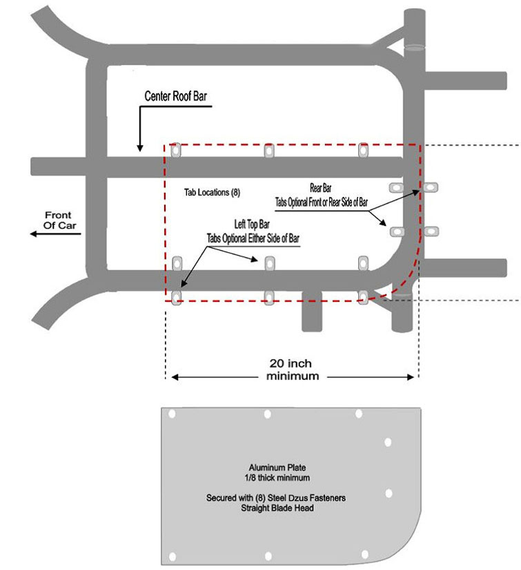
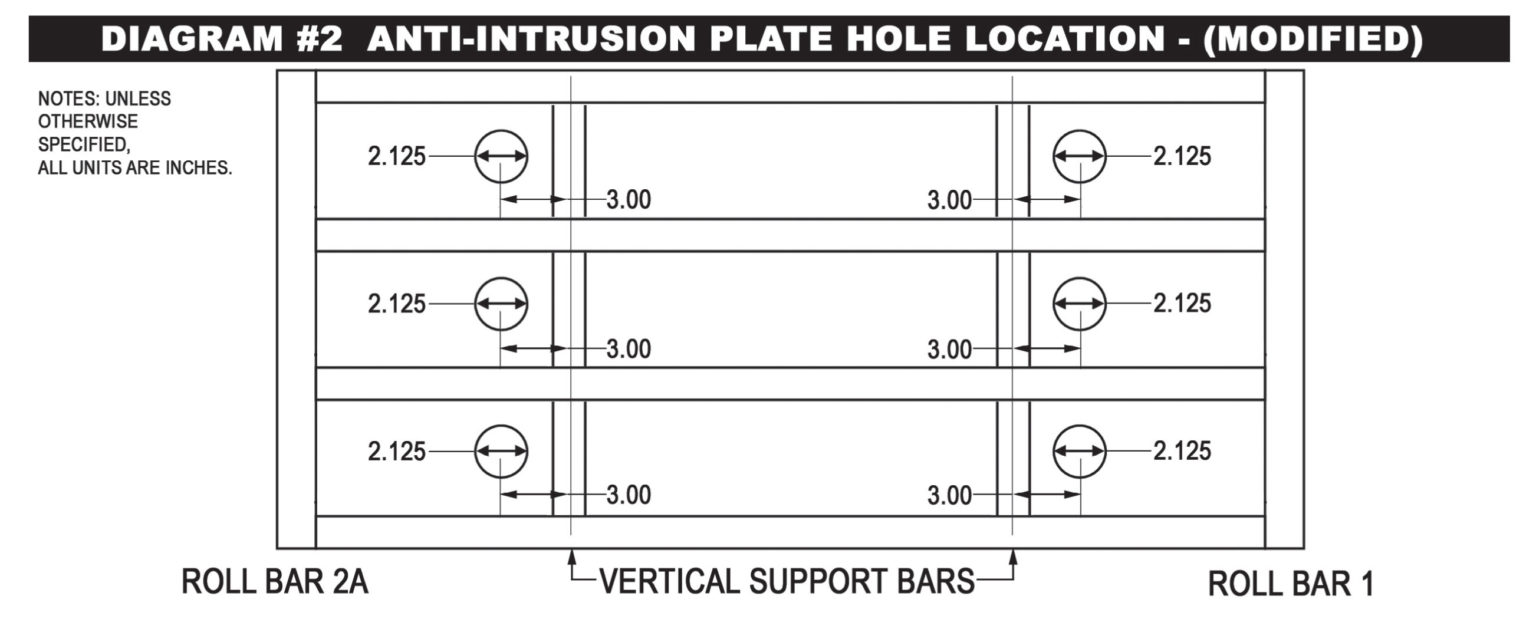
- A 13-gage (0.0897 inch thick) magnetic steel anti-intrusion plate(s) must be securely welded to the outside of the left side door bars. The anti-intrusion plate(s) must fill the area between the horizontal centerlines of the top and bottom door bars, and vertical centerlines of main roll bar (#1), and the left front roll bar leg (#2A). The plate(s) must be formed to match the curvature of the door bars. Plate(s) welded between the vertical upright bars should be as large as possible. All plate(s) must have the corners welded with one (1) inch of weld followed by a maximum of three (3) inches of surface not welded and followed again by a minimum one (1) inch weld. To facilitate emergency removal of the left side door bars (#9A), the anti-intrusion plate must have six (6), 2-1/8 inch diameter holes cut in the anti-intrusion plate, with three (3) holes forward of the front vertical supports and three (3) holes rearward of the rear vertical supports in the following locations: The upper two (2) holes must be centered vertically between the left side door bars (#9A-1&2), at an on-center distance of three (3) inches from the center of the front vertical support and the rear vertical support. The middle two (2) holes must be centered vertically between the left side door bars (#9A-2&3), at an on-center distance of three (3) inches from the center of the front vertical support and the rear vertical support. The lower two (2) holes must be centered vertically between the left side door bars (#9A-3&4), at an on-center distance of three (3) inches from the center of the front vertical support and the rear vertical support (see Diagram #2 BELOW).
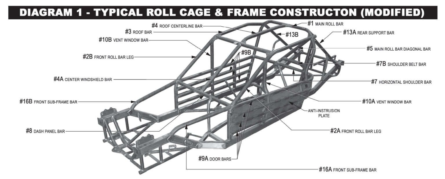
All cars must have a foot protection bar acceptable to SMS Officials installed on the left side of the roll cage. The foot protection bar must be located at or in front of the pedal assembly, when viewed from the side and above. The foot protection bar must be completely welded to the left front roll bar leg (#2A) and extend forward and be completely welded to the main frame rail or front sub-frame.
It is recommended that you run two “ear” bars on the driver’s side, with two horizontal bars connecting them, to reduce the exposure of the drivers head area. These bars should be made with 1-3/4” DOM steel tubing.
NOTICE – Competitors are solely and directly responsible for the safely of their race cars and racing equipment and are obligated to perform their duties (whether as a car owner driver or crew members) in a manner designed to minimize to the degree possible the risk of injury to themselves and others.
Rules For Pit Road:
If you choose to come down pit road during an event to have your car inspected for damage or leaks: Bring your car to the stand on pit road. Your car will be inspected (but not serviced or repaired) for damage and leaks. If your car is OK, you will be instructed to join the field at the rear of the running order. If, in the judgment of SMS pit road officials, your car has damage or leaks that are not safe, you will be done for the event.
If you are told to come to pit road for an inspection: Bring your car to the stand on pit road. Your car will be inspected for damage and leaks. If your car is OK, you will be instructed to join the field. If, in the judgement of SMS pit road officials, your car has damage or leaks that are not safe, you will be done for the event.
Drive-through penalty: If you are assessed a drive-through penalty for an on-track incident, you must come to pit road immediately, and drive through / down pit road at 25mph, rejoining the field at the exit of pit road.
Black flagged from the event: If you are black-flagged out of the event, you must come to pit road immediately.
CONTINGENCIES- Contingency Sponsors are a valuable part of the SMS program. Contingency stickers must be displayed for either product or monetary consideration. Each division will be notified as to what stickers are required to be eligible for contingency rewards. In particular, the decals must be mounted on the driver’s side of the car in such a manner that they are clearly visible in a photograph. Contingency stickers must be used as supplied by SMS. Alterations to the stickers are not permitted.