Preface
The request for new or modified parts or components not specifically addressed in the current version of this rule book must be submitted in writing, via email, to tech@staffordspeedway.com for consideration of approval on or prior to August 1, 2023 unless otherwise authorized by SMS to be considered for competition for the 2024 season.
All equipment is subject to the approval of SMS Officials. You may be assessed penalties including but not limited to: added weight, fines, loss of points, loss of handicapping, and suspension, car parts, components, and/or equipment deemed as not in compliance with these rules. Any car part, component, and/or equipment which does not conform to specifications or tolerances contained in the 2023 rule book or is not otherwise approved by SMS may not be used in competition in 2023.
By engaging in competition at SMS, you hereby agree to have read the 2023 NASCAR Weekly Racing Series rulebook, The 2023 SMS General rulebook and the 2023 SMS Late Model rulebook. You may not compete without a roof, hood, trunk lid, windshield, bumper cover, bumpers, fenders, quarter panels, air cleaner or mufflers.
All 2023 NASCAR Weekly Racing Series (NWRS for Late Model Stock) rules will be enforced for the SMS Late Models, when applicable, with the following changes and/or additions (EIRI). SMS Officials decisions regarding rules are final and non-appealable.
Driver Eligibility
20G- 1 Competing Chassis
20G – 1.3 Approved Competition Models
The following bodies are approved for the Late Model Division:
| YEAR | MAKE | MODEL |
|---|---|---|
| 2000-2013 | Chevrolet | Monte Carlo |
| 2006-2018 | Chevrolet | Impala SS |
| 2007-2019 | Dodge | Charger |
| 2006-2018 | Ford | Fusion |
| 2000-2005 | Ford | Taurus |
| 2000-2019 | Toyota | Camry |
| 2009-2013 | Cadillac | CTS |
Hood must be fiberglass or approved composite.
Roof must be steel or fiberglass.
Fenders must be aluminum, steel, poly / plastic or approved composite.
Quarters must be aluminum, steel, poly / plastic or approved composite.
Doors must be aluminum or steel.
Deck lid / trunk must be aluminum or steel.
20G- 2.1 Bodies
- Cars must have complete bodies, which includes the hood, roof, front fenders, doors, quarter panels, front and rear bumper covers.
The minimum thickness for any exterior sheet metal body part made of steel must be 24 gauge (.025”) thick.
The minimum thickness for any exterior sheet metal body part made of aluminum must be .040”. - Body mounts may be solid or adjustable, and may be made of metal, plastic or Polycarbonate.
- Installation of aerodynamic or air directional devices of any type are not permitted. Streamlining/contouring of body panels or windows is not permitted. Grilles must resemble OEM Stock in their dimension and location.
- A full windshield and full rear window is mandatory. The windshield and rear window must be installed in their OEM Stock position, and must be sealed to the window beds using removable sealers/adhesives.
- Fenders and quarter panels may not be modified except for wheel or tire clearance.
- The interior area of the car must be completely enclosed from front to rear with firewalls made of not less than 24 gage (0.025 inch thick) magnetic sheet steel. The floor area on the left side must not be lower than the top of the frame rails except directly under the seat where the floor may be dropped not lower than one (1) inch above the bottom of the frame rail. The floor area on the right side of the seat may be raised a maximum of eight (8) inches to the top of the drive shaft tunnel and extend to the right door panel. All interior panels must be welded.
- Cars must be equipped with approved front and rear bumper covers for your year/make/model. Installation of aerodynamic or air directional devices of any type are not permitted. All SMS Late Models are subject to the NASCAR LMS body measurements. SMS Officials will use NASCAR LMS templates to insure conformity. All vertical measurements listed in the NASCAR rulebook are plus one (1) inch for SMS dimensioning. With the exception of the 18¼” minimum deck lid length, all other measurements listed that say minimum or maximum are considered as exact for the SMS Late Model division. All listed tolerances are built into the templates from the manufacturers. All listed vertical body measurements are checked with car at ride height. Older Late Models and Limited Late Models with higher roof heights will be adjusted according to the rule.
20G- 2.2 Overall Car Weight
20G- 2.3 Added Car Weight
20G- 2.4 Car Weights After Race
20G- 3 Detailed Body Requirements
All side panels, nose and tail, roof and roof posts must be from the approved list.
Unapproved bodies and/or unapproved individual body panels are not permitted for competition.
For detailed body installation and guideline dimensions, refer to the body diagram pages in the Nascar Late Model Stock rulebook. OEM Stock or steel aftermarket replacement bodies may be used. Hood and roof may be made of fiberglass. Front fenders and rear quarter panels may be steel or plastic. All body panels must retain the OEM Stock appearance and dimensions as your make/model/year, and must be mounted in the OEM Stock location on the frame. Stock window openings must be maintained. All exterior chrome trim ornaments, outside mirrors and door handles must be removed. Replacement body parts must meet SMS templates. Body skirts or lower body rocker panel flares are not permitted.
All body panels, frame rails, tubing and chassis mounts (except exhaust system) must maintain a minimum of 5” ride height at all times.
20G – 3.1 Aerodynamic Devices
20G- 3.1.1 Front Air Dam
20G- 3.1.2 Rear Spoilers
Spoiler must be placed in the center (left-to-right) and at the rear edge of the trunk lid. The spoiler angle must be set at a minimum of 60 degrees. A maximum of two (2) one (1) inch wide non-adjustable supports on the front of the rear spoiler, or six (6) Five Star or ARP rear spoiler braces are permitted. All spoilers are subject to SMS Officials approval.
20G- 3.2 Glass
20G- 3.2.2 Rear Window
20G- 3.2.3 Side Window Glass/ Window Net
Quarter window openings must maintain the OEM Stock size, shape, and location for your year/make/model. Quarter windows are mandatory, and they must be flat, clear polycarbonate and must cover the entire quarter window opening. If quick release fasteners are used, they must be the flush mount type. All other fasteners must be acceptable to SMS Officials. Only one (1) air inlet in each quarter window is permitted. The maximum hose size is three (3) inches. Ducts that are installed in the direction to create vacuum (suction) are not permitted.
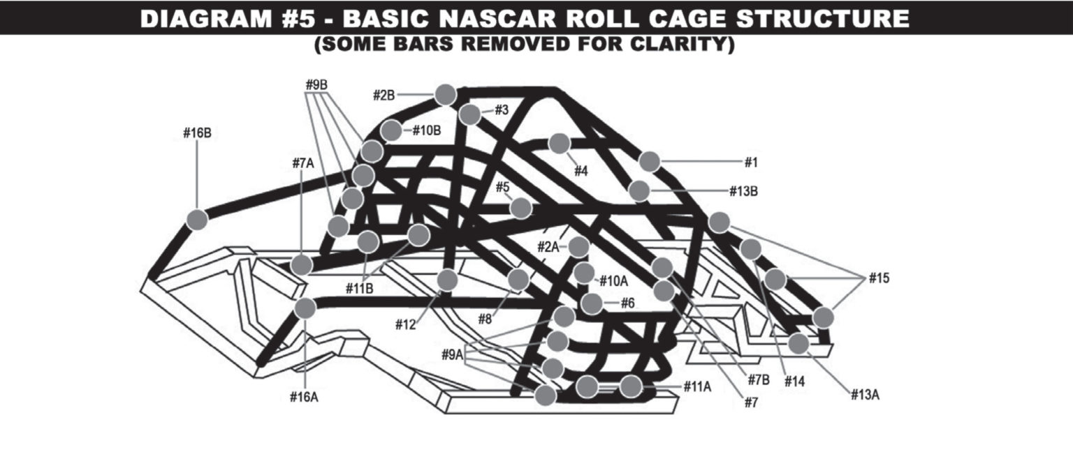
WINDOW NET– A commercially manufactured, SFI rated nylon window net must be installed in the driver’s side door window opening. It must be positioned to cover the entire window opening. Window nets may not be used beyond three (3) years from the date of manufacture. The window net must be rib type, made from minimum ¾ inch, maximum one (1) inch wide nylon material with a minimum one (1) inch and a maximum 2-1/4 inches square opening between the ribs. The minimum window net size must be 22 inches wide by 16 inches high. All window net mounts must be a minimum ½ inch diameter solid steel rod on the bottom and a minimum one (1) inch wide by 3/16 inch thick flat steel or a minimum ½ inch diameter solid steel rod on the top, with mounts welded to the roll cage. The window net must fit tight and be secured with a lever-type quick release latch. The lever must be secured by a detent ball in the lever and may be supplemented by Velcro® fastener only – pins or clips are not permitted. The latch must mount at the top in the front to roof bar (#3) and release from the inside.
20G – 3.2.4 Headlights/taillights
20G- 3.2.5 Rear View Mirror
20G- 3.4 Firewalls
- Front firewall must be no further than 2.250″ from the front edge of frame rails, and be made of minimum .031″ magnetic sheet metal with all holes covered using sheet metal a minimum of .031″ thickness. The front firewall must extend down to the top of the frame. The bottom 8.0″ may angle no more than 70 Degrees, before going upward at 90 Degrees.
- Rear firewall must be made of minimum .031″ magnetic sheet metal securely installed over the rear seat back brace and top shelf or “hat rack”, completely closing off the trunk compartment.
- The top shelf or “hat rack” must be positioned horizontal and approximately level, attaching to bar #7. On the driver side of the hat rack, there must be a containment area for the seat belts. This can be constructed by making a cut out 42″ from the back edge of the hat rack. The inverted box should go from the top of the hat rack to the top of the #6 bar. This box should be approximately 13.500″ by 8.250″ and be angled at 70 degrees and must be welded in place.
- The interior area of the car must be completely enclosed from front to rear with fire walls made of not less than 22 gage (.031 inch thick) magnetic sheet steel. The floor area on the left side must not be lower than the top of the frame rails except an area maximum 24 inches by 24 inches directly under the seat where the floor may be dropped not lower than two (2) inches above the bottom of the frame rail. The floor area on the right side of the seat may be a maximum eight (8) inches to the top of the driveshaft tunnel and extend to the right door panel. All interior panels must be welded. Door bars may not be paneled on the inside. All door bars above eight (8) inches must be visible from inside car. The floor must be sealed to the bottom of the door on both sides of the car. The rear seat area must seal to the rear firewall.
- Door bars may not be covered on the interior of the car and must be visible for inspection from the inside of the car.
Reminder for main cage construction-
You must have 4 door bars on each side, with door bars being curved, not straight, as described below in the NASCAR Weekly Racing Series Rulebook
The door bars (#9A & B), on both the left and right sides, must have a minimum of four (4) bars equally spaced from top to bottom that must be welded horizontally between the vertical uprights of the main roll bar(#1) and the front roll bar legs (#2A & B). All door bars must each be a continuous length of tubing. The top door bar on each side must maintain a minimum vertical height of 20 inches from the top of the main frame rails and match up with the intersection of the dash panel bar (#8) at the roll bar legs (#2A & B) at the front and the intersection of the horizontal shoulder bar (#7) at the main roll bar (#1) at the rear. All door bars must be convex in shape except the bottom door bar on each side which may be straight. The door bars (#9A & B) must have a minimum of six (6) vertical supports per side with two (2) equally spaced between each door bar. These supports must be made from a minimum of 1-3/4 inches by 0.090 inch wall thickness magnetic steel seamless round tubing (not numbered but shown in the left side view of Diagrams #3, #4 & #5).
20G- 3.5 Doors
- Doors may be steel or aluminum. External nerf bars or rub rails of any type are not permitted. Spreading or narrowing of the body is not permitted. Doors must have OEM Stock contour.
- Cars must have a magnet steel anti-intrusion plate minimum 0.090 inch thick, installed on the outboard side of the left side door bars. (See NASCAR rule book 20F-3.5-B for mounting instructions & diagram).
20G- 3.6 Fenders / Quarter Panels
20G- 3.7 Grilles
20G- 3.8 Hoods, Roof
- Hoods may be made of fiberglass or approved composite. The sides of the hood must seal tight to the fenders. The back of the hood (including the raised area of the non-functioning scoop) must fit tight to the windshield. The hood must be in place at all times.
- Hood must be held closed with quick release pins across the front. Quick release pins or hinges may be used across the rear.
- Holes in the hood or any functioning air scoops are not permitted. Hoods must lay flat.
- Openings or cut-outs are not permitted in the hood.
- All roofs must be the same size and shape of a production roof. Steel or fiberglass roof permitted. Roof panels must be permanently mounted in the stock position the same as a stock production roof for the year/make/model being used.
20G- 3.9 Rear Deck Lids / Trunks
20G- 3.10 Bumpers/bumper Covers
- The front and rear bumpers and/or bumper covers must be installed in the same location as far as height, width and depth as a stock factory production bumper.
- Magnetic steel tubing, a maximum size of 1-3/4 x .095 wall may be used to reinforce the front and rear bumper covers. The tubing that is used for the main structure of the bumper must not be exposed and must remain behind the bumper covers.
- The front and rear bumpers/bumper covers must be solid. Holes are not permitted.
- All front and rear bumper covers should be painted the same color as the car including bolts and rivets.
MANDATORY REAR BARS- To help create a better alignment of all “front bumper -to-rear bumper” contact, two bars made of 1 ¼” OD round magnetic steel tubing must be added to the fuel saver bar, and connect to the bottom of the main rear bumper bar. These two bars may have one 90 degree bend in them, and may be bolted or welded in place. These are the only bars that will be exposed from the bumper cover.
20G- 3.11 Identification
20G- 3.12 Body Templates
20G- 3.11 Identification
- Numbers / Graphics- All car number configuration and design is subject to approval by SMS Officials. Single or double-digit numbers are permitted. The size, color, and style of numbers must be adequate to permit prompt identification by SMS Officials at all times. Numbers must be solid, at least 18 inches high, measured vertically, excluding borders and silhouettes, must be neatly attached to or painted on both sides of the car on the center of the door. Door numbers must be a minimum of four (4) inches in width, and slant no more than 30 degrees from vertical. The tops and bottoms of all numbers must be even (not staggered). Two (2) digit numbers must have a minimum separation of two (2) inches between the numbers including borders. All graphics must have a minimum separation of two (2) inches from any number including borders. A solid number 24 inches high, excluding borders and silhouettes, must be neatly attached to or painted on the roof, reading from the driver’s side. Solid numbers, as large as possible, must be attached to or painted on the uppermost corner of the right side windshield and the right rear taillight cover. The use of number decals is acceptable if SMS Officials determine that the number is legible. Mirror foil numbers and decals are not permitted. Paint schemes using a mirrored or holographic appearance are not permitted. All car numbers are owned by and will be assigned by SMS Officials for use by the car owner. Car numbers are not transferable or assignable by the car owner.
- Decals and Advertising- SMS may refuse, restrict, or assign the size or placement of decals, identification, and advertising of any kind on a car for any reason. SMS may refuse to permit a competitor to participate in an Event if we determine that any advertising, sponsorship or similar agreement to which the Competitor (or a car owner, driver or crew member associated with the Competitor) is or will be a party, is detrimental to the sport, to NASCAR, Series Sponsor, or to the Promoter for any reason, including without limitation, the public image of the sport. Decals, advertising logos, text or identification of sponsors are not permitted on the most rearward vertical portion of the rear bumper cover. Decals, advertising logos, text or identification of sponsors are not permitted forward of the hood pins on the front of the car. Decals, advertising logos, text or identification of sponsors must not be on the roof panel unless otherwise authorized by SMS Officials. Decals, advertising logos, text or identification of sponsors must not extend past the seam between the hood and front fenders.
20G- 3.12.1 Body Templates
20E- 4 General Engine Requirements
These SMS Spec Engine rules are intended to create a standardized rule package to reduce cost and increase the level of competition. With the exception of engine machined components, all Spec Engine listed parts and components must be used as purchased, with no modifications permitted, unless otherwise noted.
20E- 5 Detailed Engine Requirements
Approved part numbers are as follows:
GM BLOCK – 10066034, 3970010, 3970014, 14010207, 14010209, 14011064, or 14016379 , or the DART SHP.
PISTONS- Wiseco Pro Tru-PT003H, JE SPR-157076, Manley-59053 Minimum ring thickness permitted is: Compression rings 1/16”, Oil ring assembly 3/16”
RODS- Manley-14104-8, 14050R-8, or Crower Sports Rods- SP3205
OIL PAN – Moroso-123412 or Canton-11-122
VALVES- Manley Intake 11596 or 11864, Manley Exhaust 11543 or 11863
CRANK- Scat Cast or Steel – 9-350-3480-5700, Callies Magnum Series, or Manley 190190.
INTAKE- second generation Edelbrock 2101
HARMONIC BALANCER- ATI 917260 or 917320 or BHJ CH-IBS-6-C
CARB SPACER- Big Haus U.S.A. # 001
FLYWHEEL- 10,000 RPM- 1019 (12.5 lbs), RAM- 1510, Flywheel must maintain a minimum weight of 12 lbs (bolts not included).
20E- 5.1 Engine Location
- Engine must be in the OEM Stock location for a V8 in your year/make/model chassis. OEM Stock engine location is: The engine must be centered from left-to-right in the chassis, and the distance between centerlines of the forward most fuel pump bolt hole to the upper idler-arm mounting bolt hole must measure 8.75” inches +/- .25” inch. All bolt holes/locations must be OEM Stock.
- The crankshaft centerline (vertical dimension) to ground may be a minimum of 12-3/4”, measured at the center of the harmonic balancer when car is at 5” ride height / blocks.
20E- 5.5 Pistons/rods
- The approved piston must retain all its manufactured dimensions and weight. The JE and Manley pistons must maintain a 2.50” pin length. Wiseco pistons must maintain a 3.00” pin length. Gas porting of any type is not permitted. All rings must be installed, working and of magnetic steel. Stainless, z-gap, gapless, or Dykes type rings are not permitted. No portion of piston may protrude above the top of the block. The minimum ring thickness permitted is as follows: Compression rings 1/16″ Oil ring assembly 3/16″.
- Only magnetic steel non-coated piston pins maintaining a minimum diameter of .927” inch are permitted. They must be contained by bushings only (no bearings of any type). Full floating pins are permitted. Wrist pins may not be coated.
- Piston pin holes must be in a fixed location in the piston and connecting rods.
- Only two-piece insert style connecting rod bearings are permitted.
- The approved rod must retain all of its manufactured dimensions and weight. Only normal engine balancing and the use of after-market bolts and nuts are permitted. No de-burring, de-flashing, polishing, grinding or lightening is permitted. Rod length must be 5.700”.
- Minimum weight for piston, pin, ring, bearing and rod assembly is 1185 grams.
20E-5.5.4 Oil Pan
20E-5.6.2 Heads
VALVES- The Manley intake valve 11596 (111 grams), Manley intake valve 11864 (114 grams), Manley exhaust valve 11543 (95 grams) or Manley exhaust valve 11863 (102 grams) must be used. Valve stems must have a minimum diameter of 11/32 inch. Valve lifter weight is 85 grams minimum. All parts must maintain production dimensions and weight.
VALVE JOB- When cutting the valve seat angles, no stone or grinding marks are permitted above the bottom of the valve guide. All cutting in reference to the valve job must be centered off the centerline of the valve guide. Competition style multi-angle valve job is permitted. The bowl area must pass the 360 degree “ball” check (the appropriately sized ball must not fall into the guide area when rolling around on the valve stem). Intake is a .787” ball. Exhaust is a .531” ball. Surfaces and/or edges where the cutter or stone has touched must not be polished. No hand grinding or polishing is permitted on any part of the head.
VALVE SPRINGS & RETAINERS- OEM Stock type magnetic steel retainers that weigh a minimum of 30 grams (retainer only) must be used. Valve springs may be single or double springs, but must be parallel wound. Barrel wound, conical wound springs, or beehive type springs are not permitted. Double springs must have a diameter between 1.450” and 1.437”. Valve springs must have a height of 1.700” to 1.800”. Retainer locks must be magnetic steel, and must be Machine 7 degree, Super 7 degree, or 10-degree types only.
20E- 5.7 Crankshaft
- The Scat Cast or Steel Crank 9-350-3480-5700, Callies Comp Star series crankshaft, or the Manley 190190 may be used. The main and rod journal sizes are .020” under for the main and .030” under for the rod journals. Stroke must be 3.480”.
- Small journal or Honda pin crankshafts are not permitted.
- Machining or polishing of the crankshaft counterweights is not permitted. Normal standard engine balancing is the only acceptable modification that can be performed on this component. No painting or Teflon coating. No capping of the counterweight holes. Crankshafts must maintain the manufacturers’ dimensions.
- Minimum crankshaft weight is 46lbs.
- The Power Bond PB1012-ss, ATI 917260, 917320, or the BHJ CH-IBS-6-C harmonic balancer must be used.
20E-5.8.1 Camshaft
20E – 5.8.2 Valve Lifters
- A .842” diameter magnetic solid steel valve lifter must be used. Roller tappets, ceramic valve lifters, tool steel solid lifters, mushroom valve lifters, and any type of mechanical assistance exerting a force to assist in closing the valve and/or push rod commonly known as rev-kits are not permitted.
- Valve lifters can weigh no less than 85 grams.
20E- 5.8.3 Rocker Arms
20E- 5.9 Intake Manifold
NOTE: SMS Officials reserve the right to swap competitors intake manifolds as part of their routine post-race tech process.
20G- 5.10 Carburetor
- Body of carburetor and metering block: No polishing, grinding or reshaping of any part. Drilling of additional holes or plugging holes is not permitted.
- The choke may be removed, but all screw holes must be permanently sealed.
- Choke Horn: Choke horn may not be removed.
- Boosters: Boosters may not be changed. Size or shape must not be altered. Height must remain standard.
- Venturi: Venturi area must not be altered in any manner. Casting ring must not be removed.
- Alterations to allow additional air to be picked up below the opening of the venturi such as altered gaskets, base plates and drilling holes into the carburetor will not be permitted.
- Base Plate: Base plate must not be altered in shape or size.
- Butterflies: The stock Holley 4412 or Stainless Steel Holly part 346 butterflies must be used. They may not be thinned or tapered. The Butterflies must remain as manufactured, and must maintain the Holley production tolerance thickness of .0438” to .0398”. Idle holes may be drilled in butterflies. Screw ends may be cut even with shaft but screw heads must remain standard.
- Throttle Shaft: Shaft must remain standard and must not be thinned or cut in any manner.
NOTE: SMS Officials reserve the right to swap competitors intake manifolds as part of their routine post-race tech process.
20E- 5.10.2 Carburetor Spacer
One standard gasket per side, maximum gasket thickness of .075” permitted.
Additional openings for the induction of air are not permitted. All spacers must be approved by SMS Officials.
20G- 5.12.1 Air Filter / Air Filter Housing
- Only a round dry type paper air filter element with a diameter of 14” and a height of 3” must be used. All air must be filtered through the element.
- The ALLSTAR Performance 25900, the AFCO 80550, or an exact equivalent air filter housing assembly must be used. This is a 3 piece assembly, the top, the base, and the sealing ring. Modifications to any part of the air filter housing assembly is not permitted.
A shield may be installed to the front area of the air filter housing up to a maximum of one half of the air filter circumference. The shield must not be higher than the height of the air filter element. Any type of air induction, ducts, baffles, tubes, funnels or anything else which may control the air entering inside of, or between the air filter and carburetor is not permitted. - The AllStar or AFCO supplied ½” sealing adapter must be used between the carb flange and the air cleaner base.
- No part of the air filter or air filter housing may protrude through the hood. The hood must lay flat and be fitted tight against the base of the windshield.
You may not compete without the air filter and air filter housing in place.
RECOMMENDED ENGINE BUILDER LIST
| R.A.D. AUTO MACHINE 80 RAVENWOOD DR. LUDLOW, MA 01056 |
Don Wood 413-583-4414 |
| T/A ENGINES 124 HILL TOP ROAD PLANVILLE, CT 06062 |
Tony Alteri 860-747-6713 |
| PERFORMANCE ENGINES 79 HAYES STREET TORRINGTON, CT 06790 |
Billy Mathes 860-489-0363 |
| PETTIT RACING ENGINES 44 OLD STATE ROAD UNIT 38 NEW MILFORD, CT 06776 |
Mike Pettit 860-354-3339 |
| LARRY’S AUTO MACHINE AIRPORT IND. PARK GROTON, CT 06340 |
Gary Espinosa 860-449-9112 |
| CARLQUIST COMPETITION ENGINES 98 FALLS AVE. OAKVILLE, CT 06779 |
Bill Carlquist 860-247-0742 |
| EAST COAST MACHINE 59 OLD BROADWAY NORTH HAVEN, CT 06473 |
Peter Chillemi 203-996-8767 eastcoastmachine@yahoo.com |
| AUTOMACHINE LLC. 55 NEWBERRY ROAD EAST WINDSOR, CT 06088 |
Dave Miller 860-627-9244 |
| ANDY’S AUTO MACHINE 48 LEWIS STREET PLAINVILLE, CT 06062 |
Andy Krawiec 860-793-2455 andrewkrawiec@snet.net |
| SPECIALTY PERFORMANCE ENGINES 160 OLIVER ROAD LEBANON, CT 06249 |
Brian Kowalshyn 860-917-3436 specialtyperformanceengines@hotmail.com |
20G- 6.1 Ignition System
- Electronic distributors are permitted. All electronic distributors must be in stock type housings, have stock type controls and modules, be equipped with a magnetic pickup, be gear driven, and be mounted in the stock location. Billet distributor housings are permitted.
- Single or dual point camshaft driven distributors are permitted.
- Only one (1) ignition coil is permitted and must be mounted on engine side of the firewall.
- Electronic firing module amplifier box is not permitted.
- Computerized, multi-coil, dual electronic firing module box or crank trigger systems are not permitted. Magnetos are not permitted. All ignition systems are subject to approval by SMS Officials.
- Adjustable timing controls are not permitted.
- Retard or ignition delay devices will not be permitted.
- Only the MSD #8727CT or the MSD #8728 External RPM limiter may be used. The violet wire of the MSD # 8728 must be cut back flush to the unit’s housing. The green and the white wires of the MSD # 8728 must run directly to the coil negative. The MSD # 8728 must be mounted out of reach of driver.
- Accessories to regulate the power supply are not permitted.
- The tachometer wire must run from the distributor to the tachometer along the #8 dash bar separate from any other wires and in unobstructed view for inspection. The tachometer wire must be isolated from any other wires, connections or devices. The entire length of the tachometer wire must be visible from distributor to the gauge.
- The Vacuum advance unit may be replaced with a manual non-electronic timing adjuster that does not extend more than two inches beyond the distributor housing.
- GM firing order must be 1-8-4-3-6-5-7-2.
- The manufactures cylinder identification sequence is as follows: G/M Front 5-1 6-2 7-3 8-4
20G- 6.2 Starter
20G- 6.5 Battery
Accessories to regulate the power supply will not be permitted.
20G- 6.7 Accessories
20G- 6.7.1 Radios
- The in-vehicle radio must be analog only and must not be capable of transmitting or receiving in a digitized, encrypted or scrambled format as determined by NASCAR. Keypad style and/or password protected radios will not be permitted. Scanning and/or channel hopping transmissions to or from the in-vehicle radio will not be permitted. All transmissions to and from the in-vehicle radio must be in the 450.000MHz-470.000MHz UHF range. The in-vehicle radio is not permitted to transmit or receive any type of telemetry (data) signal or information other than audio communications and must remain independent from any electronic system in the vehicle. Teams will not be permitted to rebroadcast transmissions to or from the in-vehicle radio at any time during an Event. It is strongly recommended that all in-vehicle radio frequencies be licensed for use by the Federal Communications Commission (FCC) and meet all applicable regulations and guidelines.
- Only one (1) NASCAR-approved, two-way radio and one (1) radio push to talk button will be permitted. It is not permitted to have any frequency of any Competitor installed in the radio at any time. The vehicle is permitted only one (1), approved radio wiring harness.
- At all times during practice(s), qualifying and feature events, the spotter must have radio communications with the driver and must monitor SMS Race Control on 464.5000. Spotters must be in the designated spotter location at all times during competition.
- Driver to driver radio communications will not be permitted.
20G- 6.7.2 Spotters
Waddell Communications – www.waddellcommunications.com 860-573-8821
20G- 6.7.3 Transponders
MYLAPS AMERICA
www.mylaps.com
32 Highlands Parkway Suite 104
Smyrna, GA 30082
Tel 678-816-4000
20G- 7 Engine Cooling System
20G- 7.1 Water Pump
- A stock OEM type pump must be used. Electric pumps are not permitted.
- Any serpentine, cog or V-belt pulley system is permitted. Pulleys must be steel or aluminum.
20G- 7.2 Fan
20G- 7.4 Radiator
- An OEM stock type radiator must be used in the stock location.
- All cars must be equipped with an approved overflow catch can under the hood by the right front fender. The over flow hose coming out of the catch can must run and up through a fitting in the cowl, at the base of the windshield on the right side.
20G- 8 Engine Oil Specifications
20G- 9 Engine Exhaust System
- The Beyea SSA-23N1-3SS, Dynatech 01-21900, Flowrite FR250FF, Flowrite FR275FF, Hedman 68600, Kooks stainless steel 15055, Kooks 6250200, Schoenfeld 185, or their exact equivalent headers must be used. Headers must be used as manufactured, they may not be modified, other than for interior and exterior coatings.
- Ford engine: Headers must be a commercially manufactured part using a 1-5/8” outside diameter steel primary tube. They may be a maximum of 30” in length, with a 3” outside diameter collector pipe. Primary tubes must exit down. The header collector pipe cannot be reduced at any point between the primary tube and the exhaust pipe. No merge or pyramid style collector is permitted.
- The exhaust header flange must mount directly to the cylinder head with no spacers between the flange and the cylinder head.
- The header collector must be used as supplied, and may not be modified.
- Exhaust pipes must be of 3″ dia. exhaust tubing and run from the header back to within 12” of the rear end housing, then turn down a minimum of 45 degrees. Pipes may not exit out the side of the car. Both exhaust pipes must be independent with no connection between them.
- Mufflers: – You must use two of the following: LOBAK RCM 30-12-30, Kooks R300-10, or Flowrite FR300. Modifications or repairs of any type are not permitted on the muffler. Both Muffler flanges must be intact. Mufflers must be removable for inspection.
- Thermal wrap is not permitted anywhere on exhaust system.
- Only one muffler and exhaust pipe per side of car is permitted.
- Exhaust system subject to approval by SMS Officials.
NOTE: The life expectancy for all mufflers is two years. Each team is responsible for inspecting their mufflers to insure they are not illegal due to wear. A muffler will be deemed illegal if it is missing one or more of the internal baffles. You may not compete without the mufflers.
20G – 9.3 Heat Shields
20G- 10 Engine Drive Train – Flywheel And Clutch
Aftermarket- 10,000 RPM- 1019 (12.5 lb), RAM- 1510, Flywheel must maintain a minimum weight of 12 lbs (bolts not included).
Flat surface machining allowed only on the face of the flywheel, any cutting or machining on the back side of the flywheel is not permitted.
Pressure Plate- OEM stock type 10.5” steel pressure plate must be used. See weight requirement below.
Clutch Disc- OEM stock type 10.5” steel full 360 degree disc or Magnus part # 384152F and 384152C must be used. Drilling or lightening of any part is not permitted. Solid magnetic steel fasteners must be used.
Pressure plate & clutch disc combined minimum weight – 16 lbs. (fasteners not included).
Clutch disc minimum weight 2.5 lbs. and a maximum weight of 3.8 lbs. (fasteners not included).
20G- 10.3 Bell Housing
20G- 10.4 Transmission
- Only OEM production stock 3 & 4 speed transmissions may be used. Top loader transmissions are not permitted. Gear ratio must be of stock OEM production.
- Only cast iron housings are permitted. Aluminum or magnesium transmission housings are not permitted.
- Only OEM type, steel, angle cut forward gears are permitted. Square cut forward gears are not permitted.
- The removal of first gear, or replacement of first gear with a metal spacer, in 4-speed transmissions is permitted. All other forward and reverse gears must be in working order, and they must be operational from inside the driver’s compartment. All transmissions must have a constant engagement of the input shaft with gear and countershaft with cluster gears.
- Machining or lightening of any internal rotating or non-rotating parts including gears, shafts and case is not permitted. Gun drilled transmission shafts are not be permitted. Welding on any internal part is not permitted. External oil pumps and oil coolers are not permitted.
- Additional or different from OEM bearings other than the tail-shaft, which may have roller bearings, are not permitted.
- Auxiliary, over or under drive transmissions are not permitted. High gear must have a ratio of 1 to 1 and no other gear may have a ratio higher than 1.20 to 1.
- Only fire resistant type shifter boots, secured with fasteners, acceptable to SMS Officials is permitted. The shifter boots should must meet the SFI 48.1 specification and display a valid SFI 48.1 label visible on the outside surface of the shifter boot. Quick release fasteners should not be used to secure the shifter boot. The shifter boot, when installed, should be completely sealed to the floor of the car. Installation of the shifter boot must be acceptable to SMS Officials. Shifter boots should not be used beyond three (3) years from the date of manufacture.
- Heating pads, blankets or any other heating devices are not permitted at any time.
- Transmission vent/breather hose & filter assemblies must be located within the transmission tunnel and must not extend forward of the vertical front firewall. Remote transmission reservoirs and/or fill tubes are permitted. All transmissions must contain a minimum of one (1) quart of lubricant. The shifter and all of its components must be made of steel or aluminum.
20G- 10.5 Driveshaft
- Drive shaft, universal joints, and yoke must be magnetic steel and be similar in design to the standard production type. The drive shaft must be made of one-piece magnetic steel and must either 2-3/4 inches or 3 inches in diameter.
- Two (2) 360 degree solid magnetic steel brackets with no holes or slots, not less than 2 two (2) inches wide and ¼ inch thick, must be placed around the drive shaft. The front bracket must be welded to the rear suspension crossmember and the rear bracket must be welded or bolted, with a minimum of two 3/8-inch diameter bolts on each side, to the horizontal tunnel bar (#6).
- All drive shafts must be painted white.
20G- 10.6 Rear Axle
- The center of the rear end housing must be within 1″ of the centerline of the track width, front and rear.
- Differential gears must be welded or replaced with a steel spool. Posi-traction, limited-slip or ratchet type differentials are not permitted.
- Only one-piece, magnetic steel rear end axle housings are permitted.
- Racing axles are mandatory on both sides for all GM rears. Full floating straight-cut double splined rear axles may be used. Only one-piece solid magnetic steel axles are permitted. Hollow or drilled axles are not permitted. Full floating double splined rear axle minimum weight is 9.0 lbs.
- Magnetic steel axles, drive plates, bearings, and axle housings are allowed. Aluminum parts are not permitted in or on the rear housing assembly (except for the axle caps and brackets for third link).
- Cambered rear axle housings or other cambered components (axles, drive flanges, etc.) will not be permitted. Crown type axles or spline adapters will not be permitted. A tolerance of 1-1/2 degrees of camber (positive or negative) will be permitted.
- Only magnetic steel drive plates, the same thickness on the left and right side are permitted. The drive plates must be one-piece with a single straight cut internal spline. Grease fittings are permitted on drive plates and axle caps.
- Upper Trailing Arms– A steel arm with heim joints or stock OEM type rubber mounting bushings may be used. A torque absorbing rubber bushing assembly like the ALLSTAR ALL56165 arm, or similar, is permitted. The rubber bushing diameter may not exceed 2-1/4”.
The upper arm must be a maximum of 13 inches from the vertical centerline of the rear axle to the centerline of the forward mounting point. The rear mount may be moved rearward to create a longer arm, but the forward mount point must not exceed the 13” measurement from the centerline of the rear end housing.
Shocks or springs are not permitted in or on the upper trailing arm / top link.
Panhard Bar (track bar)- A steel panhard bar with heim joints or stock OEM type rubber mounting bushings may be used. Shocks, springs, or torque absorbing bushings may not be used on the panhard bar assembly.
- Lower Trailing Arms– You must use a Stock OEM arm, DCA 17812, Johnson Chassis JCI-09-03-01M, Johnson Chassis JCI-09-03-03B, Hamm’s Welding GHC-1925 or Hamm’s Welding GHC-1950 arm. The Stock OEM, DCA, Johnson, and Hamm arms may not be modified or altered, except the Stock OEM trailing arms may be plated for added strength, which will make them equal to the DCA replacements. Lower trailing arms must attach to the frame in the OEM Stock location. Mounting brackets on the axle tubes may be moved but rear must be centered in chassis. The lower trailing arm brackets may not be longer than 6”, as measured from the bottom of the axle tube to the lower end of the bracket. Left and right brake rotors must be an equal distance from the frame rails.
Adjustable Right Lower Trailing Arm– The right side (only) lower trailing arm may be the Johnson Chassis “GM Metric” adjustable arm, the Hamm GHC-1937J adjustable arm, or the JMD Chassis 9700 adjustable arm. The adjustable arm must be installed at a length of 19-1/4” +/- 1”. The arm may not be modified or altered. - Springs must be mounted on axle housing in stock location for frame being used.
ALLSTAR Performance- 269-463-8000
DCA Fabrication- 608-781-3929
Hamm Chassis- 413-267-9100
JMD Chassis- 860-889-8218
Johnson Chassis- 704-784-5353
20G- 10.6.1 Rear Gear
GEAR RULE: Ford rear must use either a 4.86 or 5.00 final drive. GM rear must use a 4.88 final drive.
20G- 10.7 Wheels
20G- 10.8 Tires
TIRE INVENTORY- T-B-D for 2023
Each tire will carry a special bar coded serial number. The legibility of the bar code is the sole responsibility of the team. Drivers must pick up their Tire Inventory card from the Handicapping / Sign in booth and enter the barcode serial number of the tires they wish to use. Each tire barcode that is entered on the tire sheet will use one of your credits. The Tire Inventory card will be filled out and turned in to the Tech Center each week prior to the scheduled drivers meeting. Drivers that do not turn in the Tire Inventory Card on time will be penalized. Edits to the tire inventory card after it is turned in is not permitted.
Drivers that have non-inventoried tires on their car during qualifying or feature events will be penalized.
In the event a driver changes cars for qualifying or feature racing, their tire inventory must accompany them to the new car (EIRI).
The amount of extra tires allowed for longer distance feature events will be determined by SMS Officials.
If a tire cannot be identified, it will be considered illegal.
SMS Officials may change or amend these rules at any time.
20G- 10.8.1 Physical Requirements
- Minimum Tire Pressures for all inspection purposes are fifteen (15) psi for both left side tires and twenty five (25) psi for both right side tires. Air may be added to the tires to achieve only the minimum tire pressures during inspections, per a track provided tire pressure gauge.
NOTICE: Any participant competing in any event at SMS specifically agrees that they acknowledges that it is illegal to soak or treat racing tires and that said soaking or treatment of racing tires is against EPA regulations and further contains carcinogens and hazardous material which are unfit for his/her health and the health of all competitors and spectators. Any participant found violating the rule may subject to suspension.
20G- 11 Frames
- Main Frame
- A tubular magnetic steel frame must be used. Offset frames will not be permitted. The main frame side rails must be parallel and be an equal distance from the centerline of the frame. The main frame side rails must be Stock OEM “C” channel rails, Hamm’s part # GHC-664235 fabricated “C” channel rails, or fabricated as described herein: The main frame side rails must be the same size (left and right, height and width), constructed using a single tube, and must be magnetic steel box tubing three (3) inches in width by four (4) inches in height with a minimum wall thickness of not less than 1/8 inch meeting ASTM A-500 specification. The main frame side rails start at a distance of 20 inches forward of the rear axle centerline and extend forward a length of 66 inches. When measured from the outside of the left frame rail to the outside of the right frame rail, a width of 52” (for aftermarket side rails) to 54” (for stock OEM side rails) +/- ½” must be maintained. The distance from the outside edge of the main frame side rails, left and right, must be the same, measured from the centerline of the tread width, front and rear.
- Sub-frame kick outs must be constructed using a single tube and must be magnetic steel box tubing three (3) inches in height by two (2) inches in width with a minimum wall thickness of 1/8 inch meeting the ASTM A-500 specification. The sub-frame kick-outs must turn in 90 degrees to the main frame side rails and be welded to the inside ends of the main frame rails. The open ends of the sub-frame kick-outs must be closed by welding caps on the ends or bolting weight containment caps. The distance from the front of the front kick-out to the rear of the rear kick-out must be 66 inches. The front kick-out must measure 86 inches from the rear axle centerline.
- A crossmember constructed of magnetic steel box tubing, two (2) inches by two (2) inches with a minimum wall thickness of 0.083 inch meeting the ASTM A-500 specification, must be welded between the main frame side rails at a distance of 48 inches from the rear axle centerline.
- All frames must have diagonal cross bracing constructed out of (a minimum) 1” x 1” 0.065 wall thickness tubing.
- All crossmembers and diagonal bracing must be installed flush to the top of the main frame side rails. Center of crossmembers a maximum width of 12 inches may be dropped for driveline clearance. No part of the crossmembers or diagonal bracing will be permitted to extend lower than the main frame side rails.
- If the optional tubular metric frame is used, the center-to-center dimension of the main roll bar #1 and the rear axle must be a minimum of 23-1/2 inches.
- Rear Sub-Frame
- The rear sub-frame rails must be configured and attached in the same location on the left side and right side to the sub-frame kick-outs four (4) inches in from the outside edge of the main frame rails. The rear sub-frame when measured from the outside edge of the left sub-frame rail to the outside edge of the right sub-frame rail must measure 46 inches, and this width must be maintained for the entire length of the sub-frame. The rear sub-frame must angle rearward and upward at an angle between 45 degrees and 50 degrees to a maximum height of 22 inches from the ground (on five (5) inch blocks), then angle rearward parallel to the main frame rails a maximum distance of 16 inches, then angle down to a minimum height of 11 inches and a maximum height of 14 inches from the ground. The rear sub-frame must be constructed using magnetic steel box tubing, two (2) inches in width by three (3) inches in height, with a minimum wall thickness of 1/8 inch and must be similar in design and configuration to standard OEM automotive rear kick-ups.
- The rear sub-frame tail section must extend rearward at a minimum height of 11 inches and a maximum height of 14 inches, to a maximum length of 38 inches from the centerline of the rear axle. The rear sub-frame tail section side rails must be parallel to the main frame side rails and have a minimum length of 24 inches. The rear sub-frame tail section must be constructed using magnetic steel box tubing two (2) inches in width by three (3) inches in height with a minimum wall thickness of 0.083 inches.
- The rear sub-frame must incorporate the mounting locations for the rear springs, shock absorbers, panhard bar, and fuel cell, ending with a crossmember constructed of magnetic steel box tubing two (2) inches in width by three (3) inches in height with a minimum wall thickness of 0.083 inches a maximum length of 38 inches from the centerline of the rear axle.
- A reinforcement bar, made from round magnetic steel tubing, minimum 1-1/2 inches in diameter with a minimum wall thickness of 0.083 inches, must extend below the rear sub-frame section behind the fuel cell. This reinforcement bar must be as wide as the rear sub-frame rails and extend as low as the bottom of the fuel cell with two (2) vertical uprights evenly spaced between the sub-frame rails and attached to the rear crossmember. Two (2) support bars, one (1) located on each corner, must angle upwards and be welded to the rear sub-frame side rails. See the Construction Guidelines in the rear pages of the rulebook.
- Weight containers, if used, must only be attached to the inside of the frame rails and must not be lower than the bottom of the frame rails.
- The back of the rear sub frame from the center line of the rear end may be mitered to conform to the rules stated above. This will be the only mitered section allowed, excluding the front radiator support.
20H – 11.2 Front Sub-frame
- The front sub-frame must be constructed by the following guidelines: All of the vertical dimensions checked will be done at 5” ride ht. Many dimensions will come from a front frame kick-out that is eighty six (86) inches from the rear axle centerline constructed of three (3) inches high by two (2) inches wide magnetic steel tubing with a minimum wall thickness of 0.125 inch meeting ASTM A-500 specifications. The GM-Metric tubular mainframe width will be an O.E.M. dimension of fifty four (54) inches from the outside of the left frame rail to the outside of the right frame rail and a length of sixty six (66) inches starting at a point eighty six (86) inches forward from the rear axle centerline constructed using three (3) inch wide by four (4) inch high magnetic steel tubing with a minimum wall thickness of 0.125 inches.
- A GM-Metric type front steer tubular front sub-frame must be constructed using two (2) inch wide by four (4) inch high magnetic steel tubing with a wall thickness of 0.125-inch meeting ASTM A-500 specifications. The front sub-frame rails must be parallel to each other both vertically and horizontally. The front sub-frame rails must be parallel both vertically and horizontally to the mainframe rails from the jack bolts forward. All front steer assemblies must maintain a dimension of 31 inches from the center of the left side frame rail to the center of the right side frame rail at a point from the jack bolt extending forward in front of the steering assemblies. Spring bucket and jack bolts may be cut into left side and right side frame rails. Top of spring buckets will maintain a vertical height of 15- ¼ inches (+/- 1/2 inch). Jack bolts will maintain a centerline distance of 33- 1/2 inches (+/- 1/2 inch) measured at top of spring bucket from left side to right side and be located equal distance from centerline left and right. A distance of 21 inches (+/- 1/4 inch) must be maintained from the front frame kick-outs forward to the jack bolts centerline. Jack bolts will be allowed a maximum angle of five (5) degrees from vertical. The front sub frame rails may angle outwards and downwards from the jack bolts to the front frame kick-out to a maximum distance of 41 inches. If frame rails are angled outward a wishbone made from round magnetic steel seamless tubing 1- ½ inch by .083 minimum wall thickness meeting ASTM A-519 specification must extend from dash bar #8 to an area at the rear lower a-frame mount and continue to connect at an intersection of roof support bar #12 and diagonal bar # 7A. The front frame extensions using two (2) inch wide by three (3) inch high minimum wall thickness of 0.083 inch magnetic steel tubing meeting ASTM A-500 specifications must angle out and forward and extend a distance of twelve (12) inches forward of the forward most top steering box bolt to a minimum distance of 33 inches from the center of the left side frame rail extension to the center of the right side frame extension. This forward top steering box bolt will be a horizontal distance of 39 inches from the front frame kick-out and a vertical height of 15 inches (+/- 1/2 inch). (steering box bolt location will be inspected with a fixture that will read zero (0) degrees with the frame on five (5) inch ride height blocks) At a point four (4) inches in front of the top steering box bolt a two (2) inch wide by four (4) inch high magnetic steel tubing with a minimum wall thickness of 0.125 inch meeting ASTM A-500 specification must extend rearward a distance of 34 inches than angle down 30 degrees to the front frame kick-out. A distance of 24- ½ inches (+/- 1/8 inch) must be maintained from the front of the sub-frame kick-outs to the center of an O.E.M. three quarter (3/4) inch pin boss located on the mainframe centerline at the front of the front sub-frame crossmember. O.E.M. pin boss will be used for locating inspection fixtures. The front sub-frame crossmember must be mounted at the centerline of the front sub-frame at a 90 degree angle to the main frame side rails against the back of the 3/4 inch pin boss and be constructed using two (2) inch high by four (4) inch wide magnetic steel tubing with a minimum wall thickness of 0.125 inches meeting the ASTM A-500 specifications. A minimum thickness of one hundred thousandths (0.100) 12ga. magnetic steel must be used to construct the remainder of the front sub-frame crossmember. The front mounting points for the front lower a-frames must be constructed using minimum 3/16 inch thickness magnetic steel. The front mounting points for the front lower A-frames must be 9- 3/8 inches, measured from the centerline of the front sub-frame to the centerline of the mounting bolt at the front side of the mount and a vertical height of seven (7) inches (+/- ¼ inch). The rear mounting points for the lower A-frames must be constructed using minimum 3/16 inch thickness magnetic steel. The rear mounting points for the lower A-frame must be 13 inches (+/- ¼ inch) measured from the centerline of the front sub-frame to the centerline of the mounting bolt at the rear side of the mount and the vertical height will be 6- 7/8 inches (+/- 1/4 inch). Adjustable insert slugs may be used on the rear mounting bolt to maintain a distance of 22 inches (+/- 1/2 inch) from the center of the lower ball joint to the leading edge of the mainframe side rail and kick-out. A 1/2 inch round by 15 inch long solid steel pin must pass freely through these points during inspection. When measuring either the right side or left side the distance from the centerline of the bottom ball joint to the centerline of the sub-frame must be equal. The mounting plates for the upper A-frames must be welded to the top of the sub-frame rails and be parallel with the centerline of the sub frame rails. A distance of 37 inches will be maintained from the top idler arm bolt centerline to the front frame kick-out with a vertical height of 14 inches (+/- 1/4 inch). The GM-Metric tubular replacement mandrel bent front clip subframe must weigh a minimum of 95 lbs. A bare front sub-frame must be submitted to SMS Officials for weigh in and approval. Front sub-frame must be acceptable to SMS Officials before it can be used in competition.
Approved front sub-frames (front clip): Stock OEM Metric, Hamms Welding P/N GHC-54108 (mandrel or mitered), Hamm’s Welding P/N GHC-54108-Z61 (mitered w/ crossmember change), or Johnson Chassis P/N JCI 09-011. - The front frame horns may be replaced with 2” X 3” .083” square tubing from the forward most 1/2″ measuring hole to the front bumper. No other part of front frame rails can be replaced with tubing. The front cross member must remain stock. The raised portion of the front cross member may be replaced with steel flat stock welded in flush with the rest of the cross member, maintaining a minimum two inch (2”) thickness of the stock cross member for oil pan clearance only.
- Rear frame rails may be replaced with 2” x 3” .083” magnetic steel square tubing from the rear edge of stock upper crossmember back, only if following stock configuration height, width, and length. Optionally the replacement rear frame rails may extend parallel rearward maintaining a minimum width of the stock frame rails width at rear most edge of the upper crossmember. The upper crossmember may be removed.
- Frame rails may not be offset or shortened.
- Frames must measure within ¼ inch of all factory specifications for year/make/model used. All measuring cups or holes must remain unaltered.
- Tubing of a size and length that will not protrude from the stock frame may be located inside the driver’s side frame rail. All roll cage bars normally attaching to the drivers side frame rail must be welded directly to the supplemental tubing.
- Tubing may be utilized as a replacement for the stock transmission crossmember. Any non-stock replacement transmission crossmember must be located perpendicular at 90 degrees to the stock frame rails and no further towards the rear of the car than to have the rear edge of the tubing even with the rear edge of the transmission housing.
- Additional X-tubing may be added so long as the tubing connects to the crossmember and is not one continuous piece running from corner to corner of the stock frame. The X-tubing must attach within the two corners of each frame turnout. The X-tubing cannot extend past any of the frame turnouts and must not be attached to the perimeter frame rails short of the frame turnouts.
FORD FRAMES – Ford full-size frames, (LTD, Crown Victoria) 1979 and newer may be shortened to 108” wheelbase. Frame must be shortened in center section only using the same area on both sides.
20G- 12. 1 Springs
Front Coil Spring– Must meet the following:
Manufactured from round magnetic steel wire.
Have consistent wire diameter from top to bottom.
May not exceed $110 in retail advertised price.
All the coils must be active.
Must maintain consistent spacing between coils.
Must be 8-1/4” to 11” in free height.
Must be 5-1/4” to 5-3/4” in outside diameter.
Front Spring Mounts- The front coil spring mounts must be located on the lower A-frame for the bottom mount and the top mount must be a bucket-type and be welded to the front sub-frame rails and be the same on both the left and right side. The front coil spring upper mount plate must be attached to the front jacking bolt in a manner acceptable to SMS Officials. Monoball(s), excessive taper, bevels, or other devices on the end of the front jacking bolt, the front coil spring mounting plate, the front coil spring mounting bolt or in the front upper spring mount will not be permitted. The hole in the front coil spring upper mount plate must be round and must not be larger than 1/16 inch diameter than the front coil spring mounting plate bolt. The upper and lower coil spring mount must support the front coil spring for 360 degrees of each coil spring mount. The upper coil spring seat must be flat. Thrust-type bearing plates with a maximum diameter of 1-1/8 inches will be permitted between the end of the jacking bolt and the face of the spring seat. Heavy-duty solid metal jacking bolts, with a minimum diameter of 1-1/8 inches, utilizing right-hand threads, and a single thread count of not less than 12 threads per inch for the entire length of the jacking bolt, must be used. The jacking bolts must be installed, using a solid threaded sleeve welded completely into the frame spring bucket, in a manner acceptable to SMS Officials for the purpose of raising or lowering the car. Jacking bolts and the threaded sleeves must be the same thread configuration on the left and right side. Front jacking bolts will not be permitted to be located through the frame rails. The front jacking bolts when measured from the inside wall of the front sub-frame rail to the center of the jacking bolt mount must not be less than three (3) inches and not more than four (4) inches. The front jacking bolts must be mounted on the centerline of the front crossmember, plus or minus (+/-) one (1) inch. The front jacking bolts must be in the same location on both sides. The front jacking bolts must be perpendicular to the sub-frame rails. The front jacking bolts must be mounted on the vertical centerline of the lower spring bucket.
Rear Coil Springs- Must meet the following:
Each rear coil spring may not exceed 400lbs. in rate.
The spring will be checked for rate through several inches of travel, and must not be higher than 400 lbs per inch (+/-).
The spring will be checked for rate through several inches of travel, and must remain at the 400lb. rate (+/-) throughout the travel range.
Manufactured from round magnetic steel wire.
Consistent wire diameter from top to bottom.
May not exceed $110 in retail advertised price.
All the coils must be active.
Must maintain consistent spacing between coils.
Both coil ends closed and ground.
The closed ends of the coil spring must not have a gap larger than 1/8”.
Must be 10” to 15” in free height.
Must be 4-3/4” to 5-1/4” in outside diameter.
Rear Spring Mounts- All upper and lower rear coil spring mounts must be located between the rear frame side rails. Only one (1) rear jacking bolt frame mount per side will be permitted. Jacking bolts will be permitted to be located through the frame rails. The center of the jacking bolt must not extend further than the center of the frame rail from the inside edge. Jacking bolts located through the frame rails must have a solid sleeve extending through the frame from top to bottom and be welded completely into the frame rails. Heavy-duty solid metal bolts (jacking bolts), with a minimum diameter of 1-1/8 inches, utilizing right-hand threads, and a single thread count of not less than 12 threads per inch for the entire length of the jacking bolt, must be used. Jacking bolts and threaded sleeves must be the same on the left and right side. The rear jacking bolts must be mounted on the vertical centerline of the lower spring mount. The lower spring mounts must be located in the OEM position on the rear end housing. Monoball(s), excessive taper, bevels or other devices on the end of the rear jacking bolt, the rear coil spring mounting bolt or in the rear upper spring mount will not be permitted. The hole in the rear coil spring upper mount plate must be round and must not be larger than 1/16 inch diameter than the rear coil spring mounting bolt. The upper and lower coil spring mount must support the coil spring for 360 degrees of each coil spring mount. The upper coil spring seat must be flat. Thrust-type bearing plates with a maximum diameter of 1-1/8 inches will be permitted between the end of the jacking bolt and the face of the spring seat.
20G- 12. 2 Front Sway Bar
- One front Stock OEM or stock type replacement sway bar may be used. The sway bar must be magnetic steel, one-piece, and can be no larger than 1-1/4” (1.250”) in diameter. The sway bar must be used as it is manufactured. Modifications to the sway bar are not permitted. Front sway bar must mount under the frame, in the stock location, and attach to the lower A-Frames in their stock location. Splined sway bars are not permitted.
- The right side must attach to the lower a-frame with bolts or heim joints. The left side may be a bump pad configuration, or attach to the lower a-frame with bolts or heim joints.
- Rubber frame bushings may be replaced with metal bushings or eye/lollypop type mounts.
- Heim joints (spherical rod ends) may be used for attaching the sway bar ends to their mounts. Front sway bars must be for the purpose of anti-roll only. The front sway bar must freely rotate in its mounts. The movement of the front sway bar arms must not be prevented or restricted beyond that of normal use as an anti-roll bar.
20G- 12.3 Shock Absorbers
Front shocks must be installed so that the shock can extend a minimum of 2” when car is at ride height.
Rear shocks must be installed so that the shock can extend a minimum of 2” when car is at ride height.
Shocks may be swapped at any time with SMS inventory by SMS Officials.
20G- 12. 4 A-frames
- Lower A-frames must be GM Metric OEM Stock or OEM aftermarket replacement, and be mounted in the stock location. Lower A-frame must be GM Metric OEM Stock, or the following aftermarket:
Hamm’s Welding GHC-1425727 (L-R),
Hamm’s Welding GHC-1425727-10deg.-R.
Johnson Chassis JCI-09-02-01M (L-R),
Johnson Chassis JCI-09-02-01R (L-R),
The lower a-frames must be in the stock location for the chassis being run. The lower A-Frames are not allowed to be altered from OEM configuration, except for the flat surface of the right front Ball joint helix end may be cut and moved 10 degrees for ball joint bind clearance purposes only, when Chrysler screw-in type ball joint is used. The only other additions that will be allowed to the A-Frames will be the shock mount and the Sway-bar perch or mounting bracket. Lower a-frame rubber bushings may be replaced with concentric steel bushings or mono-balls. Lower ball joints may be replaced with “pressed-in” stock type extended lower ball joints in stock position or with standard factory stock OEM production Chrysler screw-in type or standard factory stock OEM production Chrysler screw-in type direct replacement ball joints in the stock location on the A-frames.
The A-Frames must be acceptable to SMS Officials.- The length of the lower a-frame must be 14-1/4 inches, from the center of the ball joint to the centerline of the mounting points. A-frames must fit SMS template. The location of the center of the lower ball joints must be an equal distance from the centerline of the front sub-frame rails plus or minus (+/-) 3/8 inches. Both lower A-frames must be the same length (no offsets permitted). The General Motors Type A-frame must be constructed using magnetic steel tubing. General Motors type A-frame must weigh a minimum 12-1/2 pounds complete with ball joint, bushings and/or monoballs, and coil spring Helix.
- Upper A-frames may be GM Metric, OEM Stock, or nonadjustable tubular magnetic steel with an aluminum or steel cross shaft, or Hamm’s Welding part number GHCupperXX (1st X is length designation and 2nd X is ball joint angle). Upper a-frame bushings may be rubber or metal, but cannot be offset.
- User rebuildable or serviceable ball joints will be permitted. Adjustable and “mono” ball joints are not permitted. Ball joints must be stock appearing, heavy-duty magnetic steel construction and must be acceptable to SMS Officials. The ball joints must not have any adjustment with the exception of a free play adjustment in the housing for the ball and socket. The total length of the ball joint pin from the top of the ball joint housing to the top of the pin must not exceed 3.375 inches for both upper and lower ball joints.
- Only one (1) non-adjustable lower A-frame front mounting hole per side in the chassis or A-frame will be permitted. Vertical adjustments for lower A-frames will not be permitted. An eccentric type adjuster or slug type adjustment may be used on the rear mounting bolts.
- Upper A-frame cross shaft may be steel or aluminum.
- Upper / lower a-frame rubber bushings may be replaced with metal but cannot be offset.
- The spring buckets in the lower A-frame must be round magnetic steel and must not exceed a maximum 6-1/2 inches in diameter. The distance from the center of the spring bucket to the center of the ball joint must be eight (8) inches plus or minus (+/-) 1/4 inches and must be the same on left and right sides. A spring seat (helix) must be bolted securely in place.
The upper and lower a-frames must be installed in the stock OEM location / stock OEM mounting points.
20G- 12. 5 Spindles And Hubs
- One piece non-adjustable, heavy-duty magnetic steel aftermarket spindles with unaltered stock pin must be used. Both left and right spindles must be of the same make, design, height, inclination and offset. Bolt on steering arms are permitted and must be made of magnetic steel.
- Offset spindles are not permitted. The measurement from the upper ball joint block to the lower ball joint block must be the same from side to side.
- Heavy duty, magnetic steel, tapered wheel bearings must be used.
Bearing spacers are not permitted. - Wide Five or Grand National hubs are not permitted. A steel or aluminum aftermarket hub with GM configuration is permitted.
- Stock track width and offset must be maintained. Two standard steel wheel bearings, a wheel bearing seal, a torque nut and a standard nut locking mechanism are the only components permitted on each spindle/hub assembly.
20G- 12. 6 Track Width
20G- 12. 7 Wheelbase
CHASSIS / BODY GROUND CLEARANCE – A minimum of five (5) inches of ground clearance must be maintained at all times measured at the lowest point of the frame rail. No part of frame, body, chassis mounts, tubing, sheet metal or bumper may be lower than 5″ from the ground. All ground clearance requirements are with the driver in the car.
20G- 12. 9 Body Height
20G- 12.11 Weight Transfer Devices
20G – 13 Steering Components
- All cars must be equipped with a magnetic steel steering shaft.
- All steering boxes must be mounted in the stock location and the stock position at an angle of not less than 10 degrees on GM type front sub-frames. Any means of raising or changing the steering box position will not be permitted.
- Tie rods, drag links, pitman arms, idler arms, and component parts must be heavy duty magnetic steel. Holes and/or other modifications in steering components that, in the judgment of SMS Officials, have been made with the intent of weight reduction will not be permitted.
- An OEM center link, or a stock type replacement is permitted.
- The following adjustable center links are permitted:
Johnson Chassis JCI-09-02 series center link
ALLSTAR Performance ALL56330 center link
Hamm’s Welding GHC-17255-LM center link
- The center top of the steering post must be padded with at least two (2) inches of resilient material acceptable to SMS Officials.
- A quick-release steering wheel coupling with a metal housing, acceptable to SMS Officials, must be used. The steering wheel coupling should meet the SFI 42.1 specification.
- Rack and pinion steering will not be permitted. All steering components must be made of magnetic steel including but not limited to, drag links, pitman arms, idler arms, steering arms, and steering boxes.
- Only magnetic steel spoke steering wheels will be permitted.
- The power steering pump must be mounted and driven off the front of the engine.
- All steering boxes must be constructed of magnetic cast steel.
- The use of two (2) universal joints, a minimum of 12 inches apart, in front of the firewall and a collapsible steering section in the steering shaft is recommended and must be acceptable to SMS Officials.
- Stock type steering box must be used. Rack and pinion steering will not be permitted.
- Inner tie rod: Tapered fit, non-threaded pin, magnetic steel tie rod end must be used on the inner tire rod. Outer tie rod: Tapered fit, non-threaded pin, magnetic steel tie rod end or heim joint (magnetic steel spherical rod end) is permitted. Tie rod sleeve: Stock OEM type or aftermarket radius rod (steel or aluminum) may be used. Tie rod sleeve bolts and/or jam nuts must be magnetic steel.
20G- 14 Brakes
20G- 14.2 – Brake Cooling
20G- 15 Fuel Specifications
- SMS has instituted an approval process for all racing gasoline. The intent of this rule is to help control costs, to eliminate very expensive fuel blends and fuel additives, to prevent engine damage from untried concoctions, and to insure that the fuels used are available to all. Only the specific fuels listed alphabetically below are permitted for use in the Late Model division for practice or competition at SMS. Any blending of fuels or use of any additives is not permitted. This list may be updated or amended from time to time.
Brand name Grade of fuel Sunoco Race Fuel 260GTX Sunoco Race Fuel Supreme These fuels are available for purchase at SMS. Several testing procedures will be utilized to insure that all racers use only one of the approved fuels. Competitors are required to indicate the single approved fuel used to SMS officials at the time of sampling Any and all fuel samples taken must exactly match all of the manufacturer’s printed specifications for that brand and grade of fuel, or penalties will result.
- Icing or cooling of the fuel system is not permitted in the garage, pit or racing area.
- Gasoline may be tested and certified at any event through the application of various chemical analyses as considered appropriate by SMS Officials. Gasoline may be checked before, during and after the racing events.
- Nothing may be placed in the fuel line other than a standard fuel filter. The use of any type of fuel catalyst or other fuel-altering devices is prohibited.
20G – 15.3 Fuel Samples
20G – 16 Fuel System
20G- 16.1 Fuel Cell
20G- 16.2 Fuel Cell Container
20G- 16.3 Fuel Cell / Container Installation
A reinforcement bar, minimum 1-1/2 inches in diameter and with a minimum wall thickness of 0.083 inch magnetic steel tubing meeting the ASTM A-519 specification, must extend below the rear frame section behind the fuel cell. This reinforcement bar must be as wide as the rear sub-frame rails and extend as low as the bottom of the fuel cell with two (2) vertical uprights evenly spaced between the rear sub-frame rails and attached to the rear crossmember. Two (2) support bars, one (1) located on each corner, must angle upwards and be welded to the rear sub-frame rails. The maximum distance permitted from the center of the rear axle to the center of the reinforcement bar is 37- ½ inches.
20G- 16.4 Fuel Filler / Vent Requirements
20G- 16.4.1 Fuel Filler
20G – 16.4.2 Fuel Cell Vent
20G – 16.5 Fuel Lines / Fuel Pump
20G – 16.5.1 Fuel Lines
20G – 16.5.2 Fuel Pump
20G- 16.5.3 Fuel Shut-off
20G- 17. 4 Roll Bars
NOTICE – Competitors are solely and directly responsible for the safety of their race cars and racing equipment and are obligated to perform their duties (whether as a car owner driver or crew members) in a manner designed to minimize to the degree possible the risk of injury to themselves and others.
CONTINGENCIES- Contingency Sponsors are a valuable part of the SMS program. Contingency stickers musty be displayed for either product or monetary considerations. Each division will be notified as to what stickers are required to be eligible for contingency rewards. The stickers must be displayed on both sides of the car. In particular, the decals must be mounted on the driver’s side of the car in such a manner that they are clearly visible in a promotional photograph. Contingency stickers must be used as supplied by SMS. Alterations to the stickers are not permitted.