Competitors
- SK Modified Rules
- Late Model Rules
- SK Light Modified Rules
- Limited Late Model Rules
- Street Stock Rules
- Street Stock 305/302 Rules
- Open Modified Rules
- General Rules
- Tire Rules & Info
- Race Payouts
- Driver Marketing Presentation
- 2023 NASCAR Weekly Series Rulebook
- 2023 NASCAR Whelen Modified Tour Rulebook
- Spring Sizzler Race Procedures
2025 SK Modified® Rules
For any technical questions, please thoroughly read these rules and any applicable NWMT rules, then email tech@staffordspeedway.com.
2025 Rule Changes
20E- 12.3 COIL OVER SHOCKS
20E- 16.1 FUEL CELL
PREFACE
The rules herein shall refer to Stafford Motor Speedway as “SMS”. These rules are intended to create safe, affordable, and fair competition. While they offer a good outline, every item cannot be covered by a written rule. If you have questions regarding something not detailed in these rules, please consult an SMS Official for clarification before proceeding. These rules are for SMS only with no expressed or implied agreement with any other speedway or series as to their interpretation, implementation and method of inspection by their technical inspectors and officials. No car, component or equipment will be considered as having been approved by reason of having previously passed through inspection unobserved. No car, component or equipment will be considered as having passed inspection for the event until the finish is made official.
The request for new or modified parts or components not specifically addressed in the current version of this rule book must be submitted in writing, via email, to tech@staffordspeedway.com for consideration of approval on or prior to August 1, 2025 unless otherwise authorized by SMS to be considered for competition for the 2025 season.
The SCD, steering coupling device, manufactured by LaPlante Racing Products, www.LaPlanteRacingProducts.com is approved.
All equipment is subject to the approval of SMS Officials. You may be assessed penalties including but not limited to: added weight, fines, loss of points, loss of handicapping, or suspension for car parts, components, and/or equipment deemed as not in compliance with these rules. Any car part, component, and/or equipment which does not conform to specifications or tolerances contained in the 2025 rule book or is not otherwise approved by SMS may not be used in competition in 2025.
By engaging in competition at SMS, you hereby agree to have read the 2025 NASCAR Whelen Modified Tour (NWMT) Rulebook, the NASCAR Weekly Racing Series (NWRS) Rulebook, the SMS General Rulebook and the SMS SK Modified® Rulebook.
All 2025 NASCAR Whelen Modified Tour (NWMT) rules and the 2025 NASCAR Weekly Racing Series (NWRS) rules, where applicable, will be enforced for the SMS SK Modifieds®, with the following changes and/or additions (EIRI).
SMS Officials decisions regarding rules are final and non-appealable.
DRIVER ELIGIBILITY – All drivers must have a Stafford Speedway SK Modified® driver’s license. Drivers competing in the SK Modified® division at SMS may cross-compete in the Late Model Division only. Drivers must be at least 16 years of age.
20E- 1.3 APPROVED COMPETITION MODELS– Approved model bodies are listed in the NASCAR Rulebook. Other models both domestic and foreign steel passenger cars may be approved for the SK Modified® division providing they are the same in body configuration and meet the spirit and intent of competitive racing in the SK Modified® division.
Detailed chassis, body and interior tin rules can be found in the NWMT rule book. Body alterations / deviations from the NWMT rulebook, other than listed here, are not permitted. The decision of SMS Officials is final and non-appealable.
You may not compete without the roof, windshield, hood, air filter or mufflers in place. Additionally, the bumpers and all nerf bars must be adequately secured to the chassis at all times. SMS Officials will pass judgment on any body / bumper / nerf bar damage prior to continuing an event. Their decisions are final and non-appealable.
20E- 2.2 OVERALL CAR WEIGHT – All specified weight requirements will be with the driver. The minimum weight at all times will be 2,645 pounds. MOPAR engines over 359 cubic inch displacement must add 6.8 pounds per cubic inch over 359. No car will be allowed to have more than 56% of the total weight as the left side weight. Proper bore & stroke for engine type must be maintained. Any car found to be under the minimum overall car weight allowance will be penalized one position for every pound under the minimum total weight.
20E- 2.3 ADDED CAR WEIGHT – Added weight must be in block form magnetic steel or lead only of no less than five (5) pound blocks (no pellets). Added weight must be securely bolted to the frame rail and painted white with the car number stenciled in black. No added weight will be permitted inside the driver’s compartment. Weight must be welded in a box or attached with two or more “grade 8’ bolts minimum 7/16” diameter.
It is the team’s responsibility to inspect their lead mounting on a regular basis. Cars that have lead come off their car will be assessed (at a minimum) a $500 safety violation fine.
20E- 2.4 CAR WEIGHTS AFTER RACE – Nothing may be added to or taken from the car to make total or left-side weight. Gas, oil or water may not be added. Wheels and tires cannot be changed, but an amount equal to one half of one percent (.5%) of the gross weight will be added for loss in weight due to race wear (minimum post-race weight of 2632 lbs.). Any car found to be under the minimum overall car weight allowance will be penalized one position for every pound under the minimum total weight.
20E- 3.1 NOSE PANEL / AIR INTAKE OPENING
A conventional aluminum nose panel must be used.
The nose panel assembly must maintain 2” of ride height clearance.
The nose panel must consist of a bottom tray, two side panels, and a top panel.
Additional panels to aid in air directional flow may be installed in the nose panel.
Any additional air directional flow panels may not extend outward from the air intake opening or any part of the nose panel.
The nose panel may be no wider than the frame rails it attaches to.
The bottom tray may not extend rearward past the harmonic balancer.
The nose panel may not extend forward beyond the rear edge of the front bumper tubing.
The top and bottom panels must attach flush to the side panels.
The top panel must have an air intake opening with a minimum of 165 square inches.
A metal mesh screen may be installed in or behind the air intake opening for debris protection.
A flat horizontal air dam (splitter) may be installed on the bottom forward lip of the nose panel.
The air dam may be no wider than the nose panel and may extend forward a maximum of 1” from the bottom tray.
The air dam may not extend forward beyond the rear edge of the front bumper tubing.
20E- 3.2.3 SIDE WINDOW GLASS/WINDOW NET – A nylon window net must be installed in the left side door window opening, and it must be positioned to cover the entire window opening. Window net should not be used beyond three (3) years from the date of manufacture. The window net must be rib type, made from minimum ¾ inch, maximum one (1) inch wide nylon material with a minimum one (1) inch and a maximum 2-1/4 inches square opening between the ribs. The minimum window net size must be 22 inches wide by 16 inches high. All window net mounts must be a minimum ½ inch diameter solid steel rod on the bottom and a minimum one (1) inch wide by 3/16 inch thick flat steel or a minimum ½ inch diameter solid steel rod on the top, with mounts welded to the roll cage. The window net, when in the closed position, must fit tight and be secured with a lever-type quick release latch acceptable to SMS Officials. The lever must be secured by a detent ball in the lever and may be supplemented by Velcro® fastener only – pins or clips will not be permitted. The latch must be mounted at the top in the front to roof bar (#3) release from the inside.
WINDSHIELD – A flat windshield is mandatory, per the NWMT rulebook, made of a minimum of 1/8” polycarbonate that extends from the left A-pillar to the #4A center windshield bar and from the roof to the cowl. A minimum of three Dzus type fasteners must be used on each of the four sides.
20E- 3.2.5 REAR VIEW MIRROR – One (1) rear view mirror must be mounted at the top of the windshield. If running a head and neck restraint system, you may run a 14″ X 2″ mirror. If not, the mirror must be no larger than 8” X 2”. No multi-image or side mirrors. Oversized mirrors maybe blacked out by the use of paint only, to obtain the 8” X 2” maximum reflective area. Spot mirrors of any size/type are not permitted.
20E- 3.5 DOORS and QUARTER PANELS– may be made of magnetic steel or aluminum.
Right Side panels: The top and bottom Door flange must match the top and bottom Quarter panel flange, creating one line/plane when viewed from the side and above.
Left Side panels: one angle or break is permitted at the door / quarter panel seam.
All Doors and Quarter panels must be flat or convex in shape, they may not be concave.
The bottom flange of the Door and Quarter panels must face inward / inboard.
The Door panels must maintain a 2” minimum ground clearance.
The Quarter panels must maintain a 7-1/2” minimum ground clearance.
Aluminum crush panels must be installed per the NWMT rulebook.
ROOF POSTS- The front roof posts may be aluminum or clear lexan. They may not be any higher than the line created from the roof attaching point to the forward most door attaching point.
The rear roof posts must be aluminum and may not be any higher than the line created from the roof attaching point to the rearward most attaching point on the quarter panel. The rear roof posts must be a minimum of 49” apart when measured across the car from left to right and may not be inboard of the rear spoiler mounting area. The general shape and any cutouts in the rear roof posts must match from left side to right side. A ¾” maximum top lip is permitted on the rear roof posts, and must face inboard.
REAR SPOILER- The spoiler must be 8” tall x 48” wide x ¼” thick clear polycarbonate. The rear panel must be no wider than 60” when measured across from left to right. The height of the top of the rear panel must be between 32” and 36”. The rear spoiler must be mounted to the top of the rear panel, aft edge, and must be centered across the back panel.
20E- 3.7 NOSE PANEL AIR INTAKE OPENING-
The top panel must have an air intake opening with a minimum of 165 square inches.
The air intake opening must be rectangular in shape.
A metal mesh screen may be installed in or behind the air intake opening for debris protection.
A flat horizontal air dam (splitter) may be installed on the bottom forward lip of the nose panel. The air dam may be no wider than the nose panel and may extend forward a maximum of 1” from the bottom tray.
The air dam may not extend forward beyond the rear edge of the front bumper tubing.
INTERIOR SHEET METAL – The rear center panel (over the fuel cell) should be made of magnetic sheet steel, 22 gauge, .031” thick, with a minimum width of 28”, and must extend from the rear vertical panel forward to the #7 roll bar, per the NWMT rulebook.
20E- 3.8 HOODS / ROOF-
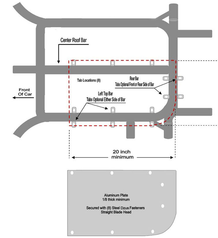
C. All roof panels must be made of magnetic sheet steel, or be an SMS approved manufactured fiberglass roof panel. All cars utilizing an approved fiberglass roof must install the (minimum) 1/8” thick aluminum anti-intrusion plate in the roll cage halo as described in the following diagram. For additional specifications on letters A. B. D. E. and F. see the NWMT rulebook. Cars may not compete without a roof or a hood.
20E- 3.11 IDENTIFICATION – All car number configuration and design is subject to approval by SMS Officials. Only single or double-digit numbers will be permitted. The size, color, and style of numbers must be adequate to permit prompt identification by SMS Officials at all times. Numbers must be solid color, at least 18 inches high, measured vertically, excluding borders and silhouettes, must be neatly attached to or painted on both sides of the car on the center of the door. Door numbers must be a minimum of four (4) inches in width, and slant no more than 30 degrees from vertical. The tops and bottoms of all numbers must be even (not staggered). Two (2) digit numbers must not overlap and must have a minimum of ¾ inch separation. A solid number 18 inches high, excluding borders and silhouettes, must be neatly attached to or painted on the roof, reading from the passenger side. A solid number a minimum of 12 inches high, excluding borders and silhouettes reading from the passenger side neatly attached to or painted at a 45 degree angle on the right front corner of the roof is also acceptable. Solid numbers, as large as possible, must be attached to or painted on the right outer nose and taillight covers. The use of number decals is acceptable if SMS Officials determine that the number is legible. Numbers, lettering, and paint schemes that utilize mirror or foil must be pre-approved. All schemes and colors are subject to SMS approval.
STAFFORD MOTOR SPEEDWAY
SK MODIFIED® SPEC ENGINE RULES
These SMS Spec Engine rules are intended and designed to create a standardized rule package to reduce cost, increase the level of competition, and to promote a better technical atmosphere by involving the engine builders in the process of technical inspection. To help keep the full integrity of the Spec Engine program intact, any published engine builder whose engine finishes in the top three may be involved in the tech process.
20E- 5 GENERAL SPEC ENGINE REQUIREMENTS- The only approved engine for Spec use is the Chevrolet 350. All parts for the Spec Engine must maintain manufacturers overall dimensions and weight. All Spec Engine parts must be installed as supplied, with no machining or modification except where noted. These SMS Spec Engine rules are intended to create a standardized rule package to reduce cost and increase the level of competition. With the exception of engine machined components, all Spec Engine listed parts and components must be used as purchased, with no modifications permitted, unless otherwise noted. We will add a list of Spec Engine component part numbers.
DETAILED SPEC ENGINE REQUIREMENTS-
All Spec Engines must use the following parts, approved part numbers are as follows:
GM BLOCK – 10066034, 3970010, 3970014, 14010207, 14010209, 14011064, 14016379 , the DART SHP, or any pre-existing GM Bow-Tie block.
PISTONS- Wiseco Pro Tru-PT003H, JE SPR-157076, or Manley 5915 must be used. The ring package used (type and thickness) must be the one designed for the piston used.
RODS- Manley-14101-8, 14050R-8, or Crower Sports Rods- SP3205
OIL PAN – Any pre-approved aluminum pan or Canton 11-196.
VALVES- Manley Intake 11596 or 11864, Manley Exhaust 11543 or 11863
CRANK- Scat Cast or Steel – 9-350-3480-5700, Callies Comp Star Series #SAF113-CM, or Manley 190190.
INTAKE- Edelbrock 7101
Carb Spacer- Big Haus USA part 002
HARMONIC BALANCER- ATI 917260 or 917320 or BHJ CH-IBS-6-C or Power Bond PB1012-SS.
The maximum decking of the block is 9.00”. Angle milling of block deck is not permitted. Offset dowel pins are not permitted. De-flashing, grinding, welding or painting of any internal area is not permitted. Maximum overbore is .060″. A maximum static compression ratio of 11.0 to 1 is permitted.
20E- 5.5 PISTONS/RODS Wiseco Pro Tru-PT003H, JE SPR- 157076, or Manley-5915 piston must be used. Manley-14104-8 or 14050R-8, or the Crower Sport Rod- SP3205 must be used.
A. The approved piston must retain all its manufactured dimensions and weight. The JE and Manley pistons must maintain a 2.50” pin length. Wiseco pistons must maintain a 3.00” pin length. Additional gas porting of any type is not permitted. All rings must be installed, working and of magnetic steel. Stainless, z-gap, gapless, or Dykes type rings are not permitted. No portion of piston may protrude above the top of the block. The minimum ring thickness permitted is as follows: Compression rings .043″ Oil ring assembly 3mm.
B. Only magnetic steel non-coated piston pins maintaining a minimum diameter of .927” inch are permitted. They must be contained by bushings only (no bearings of any type). Full floating pins are permitted. Wrist pins may not be coated.
C. Piston pin holes must be in a fixed location in the piston and connecting rods.
D. Only two-piece insert style connecting rod bearings are permitted.
E. The approved rod must retain all of its manufactured dimensions and weight. Only normal engine balancing and the use of after-market bolts and nuts are permitted. No de-burring, de-flashing, polishing, grinding or lightening is permitted. Rod length must be 5.700”.
G. Minimum weight for piston, pin, ring, bearing and rod assembly is 1168 grams.
20E- 5.5.4 OIL PAN – Dry sumps, external oil pumps or tanks or accu-sump systems are not permitted. The Canton 11-196 steel pan or any pre-approved existing aluminum oil pan may be used. Oil coolers are permitted. Only OEM in the pan magnetic steel type oil pumps are permitted. No pumps of any type may be used in the evacuation systems.
20E-5.6 HEADS – The Dart 10024266 cylinder head casting must be used. The casting part number must be purchased as completely produced by Dart, custom ordering of partial production/finishing is not permitted. The Dart casting is produced with, and must maintain a 60cc combustion chamber, a 2.02” intake valve and a 1.60” exhaust valve. Machining the valve guide bosses for seals and machining the gasket surfaces is permitted. The addition of screw-in studs, guide plates, valve spring seats, valve seals, poly-locks or jam-nuts is permitted. Coolant lines are permitted on the front/rear ends of the heads. Coolant lines are not permitted on the side of the head. Max Intake port volume is 177cc. Max Exhaust port volume is 71cc. Head gasket surface milling tolerance for SK Modified® is 0.00″ to 0.050″ from true 23.00 degrees of stock valve position. The Intake to pin measurement must be no less than 6.050”. No other machining or modifications of any kind are permitted. The ports/runners, combustion chamber, the valve angle and location must remain as produced by Dart. The EGR port may be blocked off at the intake gasket area only, by use of a metal shim on one surface of the gasket. The exterior of the casting may be painted. A maximum of 2 intake mounting holes may have HeliCoils. Intake and exhaust mounting holes may not be added or relocated. Holes must take standard dimension bolts.
VALVES- The Manley intake valve 11596 (111 grams), Manley intake valve 11864 (114 grams), Manley exhaust valve 11543 (95 grams) or Manley exhaust valve 11863 (102 grams) must be used. Valve stems must have a minimum diameter of 11/32 inch. Valve lifter weight is 85 grams minimum. All parts must maintain production dimension and weight.
VALVE JOB- When cutting the valve seat angles, no stone or grinding marks are permitted above the bottom of the valve guide. All cutting in reference to the valve job must be centered off the centerline of the valve guide. Competition style multi-angle valve job is permitted. The bowl area must pass the 360 degree “ball” check (the appropriately sized ball must not fall into the guide area when rolling around on the valve stem). Intake is a .787” ball. Exhaust is a .531” ball. Surfaces and/or edges where the cutter or stone has touched must not be polished. No hand grinding or polishing is permitted on any part of the head.
VALVE SPRINGS & RETAINERS- OEM Stock type magnetic steel retainers that weigh a minimum of 30 grams (retainer only) must be used. Valve springs may be single or double springs but must be parallel wound. Barrel wound, conical wound springs, or beehive type springs are not permitted. Double springs must have a diameter between 1.450” and 1.437”. Valve springs must have a height of 1.700” to 1.800”. Retainer locks must be magnetic steel, and must be Machine 7 degree, Super 7 degree, or 10-degree types only.
20E- 5.7 CRANKSHAFT
A. The Scat Cast or Steel Crank 9-350-3480-5700, Callies Comp Star series crankshaft #SAF113-CM, or the Manley 190190 may be used. The main and rod journal sizes are .020” under for the main and .030” under for the rod journals. Stroke must be 3.480”. If you are currently converting an existing SK Engine over to the SK Spec Engine, you may use your existing GM cast or forged steel crankshaft, and it must weigh a minimum of 50 pounds and must be 3.480” to 3.495” in stroke. You must contact the SMS Tech Staff to notify them of your intent to run this pre-existing crankshaft.
B. Small journal or Honda pin crankshafts are not permitted.
C. Machining or polishing of the crankshaft counterweights is not permitted. Normal standard engine balancing is the only acceptable modification that can be performed on this component. No painting or Teflon coating. No capping of the counterweight holes. Crankshafts must maintain the manufacturer’s dimensions.
D. Minimum crankshaft weight is 45 lbs. for the SCAT, Callies, or Manley crankshaft, and 50 lbs. for the old style SK pre-existing crankshaft.
E. The Power Bond PB1012-ss, ATI 917260 , 917320,or the BHJ CH-IBS-6-C harmonic balancer must be used.
20E-5.8.1 CAMSHAFT- K15 or P55 cast core camshafts must be used (Billet steel cores are not permitted). The maximum camshaft bearing journal size is 1.875″ (475mm). Camshaft may not exceed .550” +/- .005” lift at the valve with zero lash.
20E – 5.8.2 VALVE LIFTERS-
A. An 842” diameter magnetic solid steel valve lifter must be used. Roller tappets, ceramic valve lifters, tool steel solid lifters, mushroom valve lifters, and any type of mechanical assistance exerting a force to assist in closing the valve and/or push rod commonly known as rev-kits are not permitted.
B. Valve lifters can weigh no less than 85 grams.
20E- 5.8.3 ROCKER ARMS- Aluminum or stainless stud mounted roller rocker arms are permitted. 7/16” studs may be used. Steel 5/16” x .080” minimum wall push rods must be used. Chevrolet must run 1.5 ratio rockers. Stud-girdles are permitted, aftermarket shaft rocker systems are not permitted. Competition Cams rocker part number 1604 will be permitted.
20E- 5.9 INTAKE MANIFOLD– A second generation Edelbrock 7101 intake manifold must be used. There are no modifications or alterations permitted to the intake manifold. No porting, polishing, acid dipping, deburring, de-flashing, abrasive cleaning, internal painting, milling, cutting, drilling holes, enlarging bolt holes, matching of ports, or welding. An SMS supplied intake manifold must fit your engine complete with stock gaskets. All bolt holes must be in alignment and same size as stock. Coolant lines are only approved from the water neck to the back side of heads. The maximum thickness allowed for the Intake gasket is .064”. Note: SMS Officials reserve the right to swap competitors intake manifolds as part of their routine post-race tech process.
20E- 5.10.2 CARBURETOR SPACER –
The Big Haus USA 002 spacer must be used. One gasket per side, maximum gasket thickness of .075” permitted. The spacer may not be modified in any way. Additional openings for the induction of air is not permitted. Carb and spacer mounting hardware must be solid and must not permit air to pass through or by.
20E- 15 FUEL SPECIFICATIONS – The only approved fuel is Sunoco Supreme. Sunoco Supreme is available at Stafford Motor Speedway.
A. Icing or cooling of the fuel system is not permitted in the paddock, pit or racing area.
B. Gasoline may be tested and certified at any event through the application of various chemical analyses as considered appropriate by SMS Officials. Gasoline may be checked before, during and after the racing events.
C. Nothing may be placed in the fuel line other than a standard fuel filter. The use of any type of fuel catalyst or other fuel-altering devices is prohibited.
20E- 9 ENGINE EXHAUST SYSTEM-
A. SK Spec Engine must use the following headers:
Flowrite: Troyer 3025, CD 3035, Spafco 3055, Raceworks 3045
Kooks: Troyer SMS1048, CD SMS1438, Spafco SMS1348, Raceworks SMS1253
Beyea Performance: AMSST-23S1-SK
B. Headers must remain as manufactured, no modifications may be made to the headers.
C. The exhaust header flange must mount directly to the cylinder head with no spacers between the flange and the cylinder head. Header flange thickness may not be altered.
D. Inserts are not permitted in any part of the header or collector. Only one (1) collector allowed per side.
E. Turn-downs must be used after the mufflers, on each side. The turn-downs must be installed so that hot exhaust, engine debris, or engine flames are aimed at the ground (from pointing straight down to less than 90 degrees to horizon).
F. Kooks R35-30-10 or R35-35-10, the Flowrite FR-300 or FR-3500, or the Beyea Performance MUF3.5-SK mufflers must be used. The Muffler must be 3.5” on the inlet and outlet. Mufflers must be removable for inspection.
G. Thermal wrap is not permitted anywhere on exhaust system.
H. Only one muffler and exhaust pipe allowed per side.
Exhaust system subject to approval by SMS Officials.
J. Interior coatings are permitted.
NOTE: The life expectancy for all mufflers are two years. All owners are responsible to make sure their mufflers are in proper working order. If found not to be, the muffler will be deemed illegal (i.e., missing one or more of the internal baffles).
20E- 10 ENGINE DRIVE TRAIN – FLYWHEEL AND CLUTCH – SPEC ENGINE-
The Quarter Master 298108 or 298158, 7-1/4” two disc V-Drive, with an SFI rated 153 tooth steel OEM type ring gear/flexplate that weighs a minimum of 4.1 pounds may be used with the SK Spec Engine. Optional stock type clutch rule: A Stock OEM dimension 153 tooth steel flywheel and 10” steel clutch and pressure plate may be used. OEM type steel pressure plate and steel disc only. Solid type disc only, no paddle or button type discs. Minimum diameter 10″ clutch and pressure plate. Drilling or lightening of any part is not permitted. Steel bolts only. Flat surface machining allowed only on the face of the flywheel, any cutting on the back side of the flywheel will deem the part illegal. Spec Engine flywheels must weigh a minimum of 9 lbs. (without bolts) and be one of the following part numbers:
10,000 RPM 1019-9.5
Magnus MRPBF-95
Ram 851
20E- 5.10 CARBURETOR – A Holley two-barrel model 4412 carburetor must be used. Only Holley replacement or service parts can be used in any carburetor rework. Carburetors and/or carburetor components machined from billet materials are not permitted. All parts must be a Holley manufactured part for the 4412 model. Polishing, grinding, resizing, or reshaping of any part or orifice is not permitted. The body, base plate, metering block, and bowl must be a standard Holley 4412 part, HP parts are not permitted. OEM type gaskets, jets and power valve must be used. The diameter of every hole in carburetor must pass the standard NASCAR /SMS pin and tooling gauges as part of our routine tech process.
(1) Body of carburetor and metering block: No polishing, grinding, or reshaping of any part. Drilling of additional holes or plugging holes is not permitted.
(2) The choke may be removed, but all screw holes must be permanently sealed
(3) Choke Horn: Choke horn may not be removed.
(4) Boosters: Boosters may not be changed. Size or shape must not be altered. Height must remain standard.
(5) Venturi: Venturi area must not be altered in any manner. Casting ring must not be removed.
(6) Alterations to allow additional air to be picked up below the opening of the venturi such as altered gaskets, base plates and drilling holes into the carburetor will not be permitted.
(7) Base Plate: Base plate must not be altered in shape or size.
(8) Butterflies: The stock Holley 4412 or Stainless Steel Holly part #346 butterflies must be used. They may not be thinned or tapered. The Butterflies must remain as manufactured and must maintain the Holley production tolerance thickness of .0438” to .0398”. Idle holes may be drilled in butterflies. Screw ends may be cut even with shaft, but screw heads must remain standard.
(9) Throttle Shaft: Shaft must remain standard and must not be thinned or cut in any manner.
20E- 5.12.1 CARBURETOR AIR FILTER / AIR FILTER HOUSING
A. Only a round dry type paper air filter element maintaining a minimum 12 inches and maximum 14 inches diameter will be permitted. The air filter element must maintain a minimum of 1½” inches, maximum five (5) inches in height. All air must be filtered through the element. A nylon pre-filter may be used.
B. Only a round metal filter housing will be permitted. The top and bottom of the air filter housing must be solid with no holes. A maximum of one (1) inch lip will be permitted from the air filter element to the outer edge of the air filter housing top and bottom. The air filter housing carburetor mounting ring must have only one (1) round hole a minimum of five (5) inches in diameter. It is permissible to attach a shield to the front area of the air filter housing up to a maximum of one half of the air filter circumference. The shield must not be higher than the height of the air filter element. The air filter housing metal top and bottom must be of the same diameter. The air filter housing must be centered side to side and set level on the carburetor. No air induction, ducts, baffles, tubes, funnels or anything else which may control the air entering inside of, or between the air filter and carburetor. No plastic air filter housings or parts.
C. The bottom of the air filter element must measure within 2-1/2 inches of the carburetor’s top flange.
A spacer may be used between the carburetor and the air cleaner so long as this specification is not exceeded.
D. No portion of the hood may be higher than the bottom of the air cleaner.
You may not compete without the air filter, air filter housing or hood in place.
20E- 6.1 IGNITION SYSTEM – NASCAR approved ignition system must be used.
A. Electronic distributors are permitted. All electronic distributors must be in stock type housings, have stock type controls and modules, be equipped with a magnetic pickup, be gear driven, and be mounted in the stock location. Billet distributor housings are permitted.
B. Single or dual point camshaft driven distributors are permitted.
C. Only one (1) ignition coil is permitted and must be mounted on engine side of the firewall.
D. Electronic firing module amplifier box is not permitted.
E. Computerized, multi-coil, dual electronic firing module box or crank trigger systems are not permitted. Magnetos are not permitted. All ignition systems are subject to approval by SMS Officials.
F. Adjustable timing controls are not permitted.
G. Retard or ignition delay devices will not be permitted.
H. Only MSD 8727CT or 8728 External RPM limiters may be used. The violet wire must be cut back flush to the unit’s housing, with the green and the white wires run directly to the coil negative, mounted on the engine side of the firewall in plain view.
I. Accessories to regulate the power supply are not permitted.
J. The tachometer wire must run from the distributor to the tachometer along the #8 dash bar separate from any other wires and in unobstructed view for inspection. The tachometer wire must be isolated from any other wires, connections, or devices. The entire length of the tachometer wire must be visible from distributor to the gauge.
K. The Vacuum advance unit may be replaced with a manual non-electronic timing adjuster that does not extend more than two inches beyond the distributor housing.
20E- 6.3 ALTERNATOR – A functioning 12-volt single alternator system is optional.
20E- 6.4 STARTER – A stock type starter must be used. The starter must be in stock position and operative at all times.
20E- 6.5 BATTERY – One (1) 12-volt Gel or Glass Mat type battery with a minimum weight of 17 lbs. is mandatory. The battery must be located between the frame rails under the hood or the floor of the car. If located under the floor, the battery must be completely encased, if located under the hood the battery must have a suitable cover. The battery must not be forward of the radiator or rear of the rear end housing of the car. The battery location must be acceptable to SMS Officials.
20E- 6.7.1 RADIOS
A. The in-vehicle radio must be analog only and must not be capable of transmitting or receiving in a digitized, encrypted, or scrambled format as determined by SMS /NASCAR. Keypad style and/or password protected radios will not be permitted. Scanning and/or channel hopping transmissions to or from the in-vehicle radio will not be permitted. All transmissions to and from the in-vehicle radio must be in the 450.000MHz-470.000MHz UHF range. The in-vehicle radio is not permitted to transmit or receive any type of telemetry (data) signal or information other than audio communications and must remain independent from any electronic system in the vehicle. Teams will not be permitted to rebroadcast transmissions to or from the in-vehicle radio at any time during an Event. It is strongly recommended that all in-vehicle radio frequencies be licensed for use by the Federal Communications Commission (FCC) and meet all applicable regulations and guidelines.
B. Only one (1) SMS / NASCAR-approved, two-way radio and one (1) radio push to talk button will be permitted. It is not permitted to have any frequency of any Competitor installed in the radio at any time. The vehicle is permitted only one (1), approved radio wiring harness.
C. At all times during practice(s), qualifying and the Race the spotter must have radio communications with the driver and must monitor the SMS Race Control frequency. Spotters must be in the designated spotter location at all times during competition.
D. The radio frequency being used will be made available to SMS Officials.
E. Driver to driver radio communications will not be permitted.
20E- 6.7.2 SPOTTERS – Spotters are mandatory. Every car must have a spotter monitoring SMS race control by way of scanner or radio, located in front of SMS Race Control tower with radio communication to their car. Cars that do not follow directives from Race Control via their spotter may be black flagged and removed from the event, and the spotter suspended from competition.
Waddell Communications www.waddellcommunications.com 860-573-8821
20E- 6.7.3 TRANSPONDERS – Transponders are required on the cars at all times. See the SMS General Rules for locating transponders properly. Any car not registering a transponder signal during practice may be black-flagged to be made aware of their scoring transponders failure and is required to remedy it before proceeding further in the event.
Mylaps America
www.mylaps.com
32 Highlands Parkway Suite 104
Smyrna, GA 30082
Tel 678-816-4000
20E- 7 ENGINE COOLING SYSTEM – Only Water or SMS approved coolants or additives may be used in the cooling systems. Ethylene Glycol or Propylene Glycol coolants are not permitted.
20E- 7.1 WATER PUMP
A. A stock OEM type pump must be used. Electric pumps are not permitted.
B. Any serpentine, cog or V-belt pulley system is permitted.
20E- 8 ENGINE OIL SPECIFICATIONS – The use of combustion enhancing oils or additives is not permitted.
20E- 10 ENGINE DRIVE TRAIN – FLYWHEEL AND CLUTCH – The Quarter Master 298108 or 298158, 7-1/4” two disc V-Drive, with an SFI rated 153 tooth steel OEM type ring gear/flexplate that weighs a minimum of 4.1 pounds may be used in with the SK Spec Engine. Optional stock type clutch rule: A Stock OEM dimension 153 tooth steel flywheel and 10.5” steel clutch and pressure plate may be used. OEM type steel pressure plate and steel disc only. Solid type disc only, no paddle or button type discs. Minimum 10.5″ clutch and pressure plate. Drilling or lightening of any part is not permitted. Steel bolts only. Flat surface machining allowed only on the face of the flywheel, any cutting on the back side of the flywheel will deem the part illegal. The following weights are the minimum allowed for each part:
Flywheel only (no bolts) – Non-Spec Motor 12.5 LBS.
Pressure plate, Cover, & Solid Disc (no bolts) 16 LBS.
The steel solid disc (no bolts) must maintain a minimum weight of 2.5 pounds and a maximum weight of 3.8 pounds after the combined weight has been determined.
20E- 10.3 BELL HOUSING – Only a commercially manufactured magnetic steel bell housing may be used. The bell housing must enclose the flywheel 360 degrees with minimum 3/16” inch magnetic steel. Any modifications you make to the bell housing must be done with 3/16” steel and welded in place (no bolt on pieces). A commercially manufactured bell housing (like the Quarter Master 008110440) with a bolt on bottom cover may be used. An opening no larger than 3 ½ x 4 inches may be used for throw out bearing access. This hole may be covered with sheet metal.
20E- 10.4 TRANSMISSION- The GM OEM production stock 3 or 4 speed transmission (top loader not permitted), Richmond two speed transmission (see approved part numbers below), or the Jerico 2SP (see approved part numbers below) transmission must be used.
A. All transmissions must have a constant engagement of the input shaft with gear and countershaft with cluster gears.
B. High gear must have a ratio of 1 to 1 and no other gear may have a ratio higher than 1.20 to 1.\
C. The shifter and all of its components must be aluminum or steel.
D. Five-speed transmissions, with gears removed are not permitted. Quick change transmissions are not permitted.
E. Automatic or semi-automatic transmissions are not permitted.
F. Machining or lightening of any internal rotating or non-rotating parts including gears, shafts, and case are not permitted. Gun drilled transmission shafts are not permitted. Welding on any internal part is not permitted. Lightweight parts, machining, coatings, or special bearing upgrades are not permitted.
G. Additional or different from OEM bearings other than the tail-shaft, which may have roller bearings, are not permitted.
H. The transmission must be a “side shift” unit. Top shift transmissions are not permitted.
GM OEM Transmission-
OEM Stock cast iron, aluminum or magnesium transmission housings, or the Magnus part number MRPSA-1009 housing is permitted. The OEM Stock transmission side cover must be used. Removal of first gear or replacement of first gear with a metal spacer, in 4-speed transmissions is permitted. All other forward and reverse gears must be in working order, and they must be operational from inside the driver’s compartment. Only OEM type, steel, angle cut forward gears are permitted. OEM gear ratios must be used. Lightweight parts, machining, coatings, or special bearing upgrades are not permitted.
Richmond Two Speed-
Modification of the dog-ring and slider (high gear only) in Richmond 2-speed transmissions is permitted. The following Richmond 2-speed transmission part numbers are the only approved Richmond part numbers: 7020010X, 7020026X, 7027010X, 7027026X, the X representing Richmond’s ratios letter designator. The following Richmond produced low gear ratios are the only approved ratio for use in the Richmond 2-speed transmission: 1.2250, 1.3391, 1.4588, 1.5956, 1.7442. Lightweight parts, machining, coatings, or special bearing upgrades are not permitted.
Jerico 2SP-
The Jerico oval track 2speed transmission (part # 2SP, base model) as produced by Jerico is permitted.
The Jerico 2 speed transmission may be run, with only the following “Low Gear’ options allowed: 1.2250 to 1.7100, and “High Gear” must be 1:1. No modifications or options are allowed to the base Jerico 2SP.
The addition of any optional parts (other than base model supplied / needed), and/or any lightweight parts, machining, coatings, or special bearing upgrades are not permitted.
20E- 10.6 REAR AXLE
A. Full floating magnetic steel double splined rear axles must be used.
B. All axles must be a minimum of 7.00 pounds, and a minimum of 1.115 outer diameter.
C. Only magnetic steel axles, bearings, and axle housings are permitted.
D. Only one-piece, magnetic steel axles will be permitted. The axle splines must be straight cut, not crowned. Crown type axle splines will not be permitted.
E. Cambered rear axle housings or other cambered components will not be permitted. A tolerance of 1½ degrees of camber (positive or negative) will be permitted.
F. Only aluminum or steel drive plates, the same thickness on the left and right side will be permitted. The drive flange splines must be straight cut, not crowned.
G. Only ten (10) inch ring gear and housings are permitted.
H. Thermal dispersant coatings are not permitted.
GEAR RULE – Quick Change rears must use a 4.11/4.12 (8/33 teeth), 4.57 (7/32 teeth), or 4.86 (7/34 teeth) 10” diameter ring & pinion gear set.
The 4.12 ring & pinion QC rear may use gear sets 25 (20/22), 12 (26/29), 7 (23/26), 7A (21/24), 17 (26/30), 17A (24/28) or 8A (23/27).
The 4.57 ring & pinion QC rear may use gear sets 1 (21/21), 2 (27/28), 5 (24/25), 15A (21/22) or 15 (19/20).
The 4.86 ring & pinion QC rear must use gear set 1, tooth count of 21/21.
Straight rears may use 4.86 maximum to 4.56 minimum, 10″ diameter ring & pinion.
20E- 10.8 TIRES – Hoosier Tire East of Manchester, CT is the sole tire supplier for the SK Modified Division. The approved compounds are Hoosier 27/13-15 M450 and Hoosier 26/13-15 M30. All tires used at SMS must be purchased at the track on race day. SMS Officials may confiscate and/or impound tires at any time for inspection. The JTR Eagle PPM tire chemical tester will be set at a fixed level and will be strictly enforced throughout the 2025 season.
Each tire will carry a special bar coded serial number. The legibility of the bar code is the sole responsibility of the team. Drivers must use the Stafford Speedway Tire App (driver.staffordspeedway.com) for tire inventory and allotment.
Drivers that have non-inventoried tires on their car during qualifying or feature events will be penalized.
In the event a driver changes cars for qualifying or feature racing, their tire inventory must accompany them to the new car (EIRI).
The amount of extra tires allowed for longer distance feature events will be determined by SMS Officials.
If a tire cannot be identified, it will be considered illegal.
SMS Officials may change or amend these rules at any time.
20E- 10.8.1 TIRES PHYSICAL REQUIREMENTS
A. Minimum circumference of right rear tire @ 20 psi. is 84″.
B. Minimum Tire Pressures for all inspection purposes are ten (10) psi for both left side tires and fifteen (15) psi for both right side tires. Air may be added to the tires to achieve only the minimum tire pressures during inspections, per an SMS provided tire pressure gauge.
NOTICE: A participant competing in any race at SMS specifically agrees that he/she acknowledges it is illegal to soak or treat racing tires and that said soaking or treatment of racing tires is subject to suspension.
20E – 12.1 COIL SPRINGS – Only coil spring suspension will be permitted. The suspension and coil springs at all four (4) wheels must be active and permit suspension movement in compression and rebound. All downward chassis movement while the race vehicle is in competition must be limited only by the normal increasing stiffness of the springs or the bottoming of the chassis against the race track, whichever occurs first. Any device or procedure that in the judgment of SMS Officials attempts to detract from or compromise the above will not be permitted, including “coil-bind”. Any type of chassis travel limiter, used in compression or rebound, will not be permitted. Front shocks must have a minimum of 2″ of piston available for spring travel in compression. All coil springs must not be colder than ambient temperature.
A maximum of two full (360 degree) non-adjustable spring rubbers are permitted in the coil springs.
Shock/Coil over boots or bags are not permitted.
Coil Over Springs:
1. Coil over springs must mount to the lower A-frames.
2. Strut bars will not be permitted for mounting of coil over front springs.
3. Coil over springs must be manufactured from one solid piece of heavy-duty magnetic round steel (flat or oval wire is not permitted) and must be constructed with both coil ends closed and ground. One inactive coil on each end of the coil spring is permitted.
4. Only one (1) spring per wheel will be permitted.
5. Coil springs may be coated but coating thickness and material must be acceptable to SMS Officials.
6. All active coils of the spring must have the same coil spacing, same wire diameter, and same inside and outside diameter. The first and last coils may be different due to having closed and ground ends.
7. Progressive or digressive rate springs will not be permitted.
8. Front coil must be a minimum of 8” in free height and a minimum of 250 lbs. per inch rating. You may not use any type of device to alter the load on the front springs, other than the normal loading of the coil-over nut.
Rear coil must be a minimum of 8” in free height.
20E – 12.2 SWAY BARS (ANTI-ROLL BARS) Front sway bar must be for the purpose of anti-roll only. The front sway bar must freely rotate in its mounts. The movement of the front sway bar arms must not be prevented or restricted beyond that of normal use as an anti-roll bar.
A. Only magnetic steel front sway bars will be permitted.
B. Rear sway bars (anti-roll bars) will not be permitted.
SMS reserves the right to set and enforce a maximum sway bar spring rate.
20E- 12.3 COIL OVER SHOCKS –
The following shocks are permitted for competition in 2025:
JRI – 200-426 with piston # JRI14511778-A and 200-427 with piston # JRI14511778-A
Pro – AC series
QA-1 – 6Q Series (formerly 62 Series)
Penske – 7500 series or 7150 series with piston #XXX
Shocks will be disassembled and/or dyno’d for inspection and comparison.
The quantity and the thickness of factory supplied shims on the piston may be altered, all other components must remain as manufactured.
The piston shim stack and the shock oil are the only components you may change, every other component must be as factory produced by the shock manufacturer.
All shocks must be single adjustable, available to all competitors “race ready” with a published price of $440 or less ready to race, less any separate coil-over kits.
Piston part numbers
All shocks subject to SMS Officials’ approval.
20E- 12.5 SPINDLES, WHEEL BEARINGS and HUBS – Front spindles must be linked to frame utilizing two individual tethers per spindle. All tethers and their installation must be acceptable to SMS Officials. Low drag components (excluding seals) are not permitted. The use of oil filled hubs, oiled bearings, low friction bearings, non-steel bearings, coated or polished spindles, bearings or races will not be permitted. Two standard steel wheel bearings, a wheel bearing seal, a torque nut and a standard nut locking mechanism are the only components permitted on each spindle/hub assembly.
E. Oil filling of any spindles, wheel bearings or hubs is not permitted.
20E- 12.6 TRACK WIDTH REQUIREMENTS
A. All cars must maintain the following track width requirements. A minimum front and rear track width of 82 inches and a maximum track width of 83-3/4 inches will be permitted. The track width will be determined by measuring the left outside wheel (rim) bead surface to the right outside wheel (rim) bead surface at spindle height.
B. Aluminum or steel spacers will be permitted to utilize the maximum allowable track width. Spacers must be acceptable to SMS Officials.
20E- 12.8.2 GROUND CLEARANCE REQUIREMENTS – The frame rail and sheet metal ground clearance will be a minimum of two (2) inches. All ground clearance requirements will be measured with the driver in the car.
Officials will check ground clearance / ride height before and after feature events.
The nose panel, frame rail and door panel must maintain a 2″ minimum ground clearance / ride height at all times.
20E- 14.1 BRAKE COMPONENTS
A. Four wheel disc brakes are mandatory. Only magnetic cast iron or cast steel round circular rotors permitted. Only metal brake calipers will be permitted. Drilled, slotted or grooved rotors are not permitted. Only factory dust cleanouts are permitted. Dust cleanouts should not exceed .038 in depth. If the dust cleanout exceeds .038 in depth, the rotor may be deemed illegal. The brake rotors must be bolted directly to the hubs. Floating brake rotors will not be permitted.
B. Only Single stage master cylinders are permitted. All brake components are subject to SMS Officials approval.
20E- 14.2 – BRAKE COOLING Electric blowers are not permitted for cooling purposes in brake duct systems. Additionally, electric blowers are not permitted anywhere on the car for cooling (i.e. brakes, rear end, etc.).
20E- 15 FUEL SPECIFICATIONS – The only approved fuel for any SK engine is Sunoco Supreme. Sunoco Supreme is available at Stafford Motor Speedway.
A. Icing or cooling of the fuel system is not permitted in the paddock, pit or racing area.
B. Gasoline may be tested and certified at any event through the application of various chemical analyses as considered appropriate by SMS Officials. Gasoline may be checked before, during and after the racing events.
C. Nothing may be placed in the fuel line other than a standard fuel filter. The use of any type of fuel catalyst or other fuel-altering devices is prohibited.
20E- 16 FUEL SYSTEM – See NWMT rulebook
20E- 16.1 FUEL CELL – Must meet NASCAR specifications with a fuel cell bladder made of a material that returns to its original size and shape after deformation. Rotational molded bladders are not permitted. It is highly recommended that the fuel cell bladder be no more than six (6) years old. Competitors must provide bladder model, serial number, and date(s) to SMS Officials before competing. If a gas cap is used it must be painted white with the car number on it for identification.
The approved fuel cells at SMS are as follows:
ATL – Super Cell 100, 200 and 500 Series
Fuel Safe – Sportsman Cell and Pro Series Cell
Schultz Engineered Products – SRP Ultimate Series
20E- 16.2 FUEL CELL CONTAINER – Fuel cell container must be colored RED. See NWMT rulebook.
20E- 16.5.3 FUEL SHUT-OFF – A 1/4-turn fuel shut-off valve of minimum 3/8-inch NPT with minimum 4-inch handle is required in the fuel line. The fuel shut-off valve must be located 8-inches inboard of the passenger side frame rail’s outside edge and 24-inches forward of the main roll bar (#1 bar). The fuel shut-off valve must be mounted securely to the underside of the driver’s compartment sheet metal. The fuel shut-off valve shank must protrude through a maximum 1-inch diameter hole in the sheet metal to the interior of the driver’s compartment. The fuel shut-off valve handle must be parallel with the sheet metal that the valve is mounted to. The fuel shut-off valve handle must be a minimum of 4-inches in length, red in color with a minimum of 1-inch clearance from the sheet metal throughout its full travel. A minimum 6-inch by 6-inch square area must be painted white with the fuel shut-off valves’ ON and OFF positions clearly labeled with 1/2-inch tall, black in color lettering. The shut-off valve must rotate clockwise from a ON position with the handle parallel with the frame rail, pointing towards the rear of the car, to the OFF position with the handle perpendicular to the frame rail pointing toward the driver.
NOTICE – Competitors are solely and directly responsible for the safely of their race cars and racing equipment and are obligated to perform their duties (whether as a car owner driver or crew members) in a manner designed to minimize to the degree possible the risk of injury to themselves and others.
CONTINGENCIES – Contingencies are a valuable part of the SMS program. Contingency stickers must be displayed for either product or monetary considerations. Each division will be notified as to what stickers are required. To be eligible for contingency rewards the stickers must be displayed on both sides of the car in such a manner as to be clearly visible in a photograph.
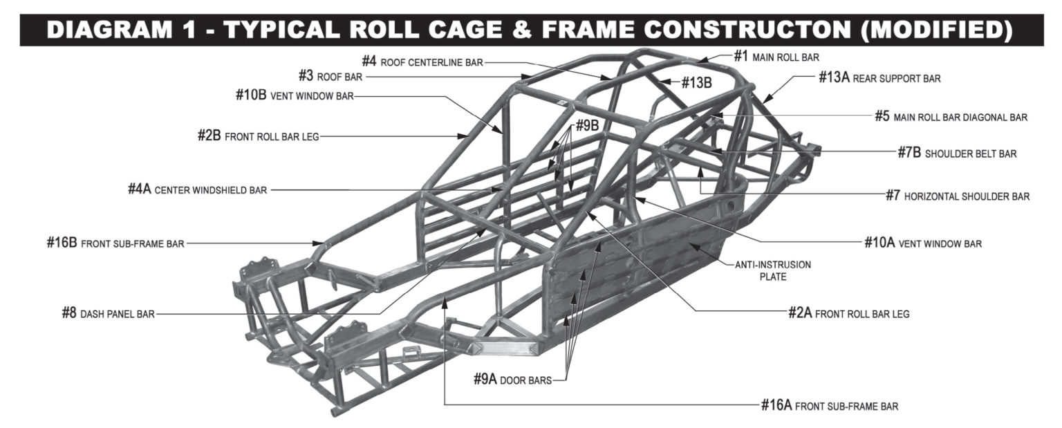
20E – 18 ROLL BARS – (8) – (A) The door bars (#9 A & B), on both the left and right sides, must have a minimum of four (4) bars equally spaced from top to bottom that must be welded horizontally between the vertical uprights of the main roll bar (#1) and the front roll bar legs (#2 A & B). The top door bar on each side must maintain a minimum vertical height of 15-1/2 inches from the top of the main frame rails to its centerline and match up with the intersection of the dash panel bar (#8) at the roll bar legs (#2A & #2B) at the front and the intersection of the horizontal shoulder bar (#7) at the main roll bar (#1) at the rear. All door bars must be convex in shape. The door bars (#9 A & B) must have a minimum of six (6) vertical supports per side with two (2) equally spaced between each door bar. These supports must be made from a minimum of 1-3/4 inches by 0.090 inch wall thickness magnetic steel seamless round tubing (not numbered but shown in the left side view of diagram #3). Right side door bars must cover a minimum of 25 inches of door length and may be either four (4) horizontal bars with six (6) vertical studs or two (2) horizontal bars and two (2) bars configured in an X design. If the X design is used, a vertical bar must connect through the center of the X from the top horizontal bar to the frame.
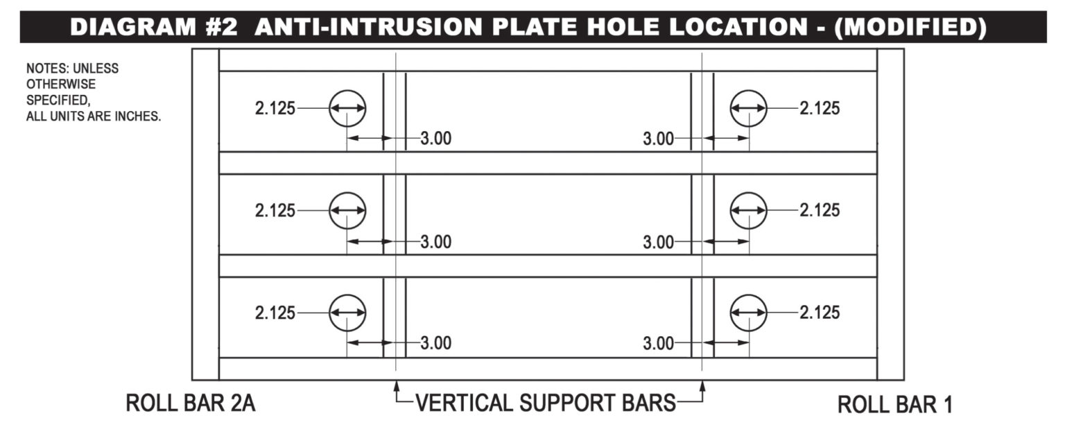
(B) A 13 gage (0.0897 inch thick) magnetic steel anti-intrusion plate(s) must be securely welded to the outside of the left side door bars. The anti-intrusion plate(s) must fill the area between the horizontal centerlines of the top and bottom door bars, and vertical centerlines of main roll bar (#1), and the left front roll bar leg (#2A). The plate(s) must be formed to match the curvature of the door bars. Plate(s) welded between the vertical upright bars should be as large as possible. All plate(s) must have the corners welded with one (1) inch of weld followed by a maximum of three (3) inches of surface not welded and followed again by a minimum one (1) inch weld. To facilitate emergency removal of the left side door bars (#9A), the anti-intrusion plate must have six (6), 2-1/8 inch diameter holes cut in the anti-intrusion plate, with three (3) holes forward of the front vertical supports and three (3) holes rearward of the rear vertical supports in the following locations: The upper two (2) holes must be centered vertically between the left side door bars (#9A-1&2), at an on-center distance of three (3) inches from the center of the front vertical support and the rear vertical support. The middle two (2) holes must be centered vertically between the left side door bars (#9A-2&3), at an on-center distance of three (3) inches from the center of the front vertical support and the rear vertical support. The lower two (2) holes must be centered vertically between the left side door bars (#9A-3&4), at an on-center distance of three (3) inches from the center of the front vertical support and the rear vertical support (see Diagram #2, in the rear pages of the rulebook).
(9) All cars must have a foot protection bar acceptable to SMS Officials installed on the left side of the roll cage. The foot protection bar must be located at or in front of the pedal assembly, when viewed from the side and above. The foot protection bar must be completely welded to the left front roll bar leg (#2A) and extend forward and be completely welded to the main frame rail or front sub-frame.
It is recommended that you run two “ear” bars on the driver’s side, with two horizontal bars connecting them, to reduce the exposure of the drivers head area. These bars should be made with 1-3/4” DOM steel tubing. These bars may be plated, similar to the drivers door bars, for added protection in this area.
CONTINGENCIES- Contingency Sponsors are a valuable part of the SMS program. Contingency stickers must be displayed for either product or monetary consideration. Each division will be notified as to what stickers are required to be eligible for contingency rewards. In particular, the decals must be mounted on the driver’s side of the car in such a manner that they are clearly visible in a photograph. Contingency stickers must be used as supplied by SMS. Alterations to the stickers are not permitted.
RECOMMENDED ENGINE BUILDER LIST
| R.A.D. AUTO MACHINE 80 RAVENWOOD DR. LUDLOW, MA 01056 |
Don Wood 413-583-4414 www.radautomachine.com |
| T/A ENGINES 124 HILL TOP ROAD PLANVILLE, CT 06062 |
Tony Alteri 860-747-6713 |
| PERFORMANCE ENGINES 79 HAYES STREET TORRINGTON, CT 06790 |
Billy Mathes 860-489-0363 |
| PETTIT RACING ENGINES 44 OLD STATE ROAD UNIT 38 NEW MILFORD, CT 06776 |
Mike Pettit 860-354-3339 |
| LARRY’S AUTO MACHINE AIRPORT IND. PARK GROTON, CT 06340 |
Gary Espinosa 860-449-9112 www.larryspower.com |
| CARLQUIST COMPETITION ENGINES 98 FALLS AVE. OAKVILLE, CT 06779 |
Bill Carlquist 860-247-0742 |
| EAST COAST MACHINE 59 OLD BROADWAY NORTH HAVEN, CT 06473 |
Peter Chillemi 203-996-8767 eastcoastmachine@yahoo.com |
| AUTOMACHINE LLC. 55 NEWBERRY ROAD EAST WINDSOR, CT 06088 |
Dave Miller 860-627-9244 |
| ANDY’S AUTO MACHINE 48 LEWIS STREET PLAINVILLE, CT 06062 |
Andy Krawiec 860-793-2455 andrewkrawiec@snet.net |
| SPECIALTY PERFORMANCE ENGINES 160 OLIVER ROAD LEBANON, CT 06249 |
Brian Kowalshyn 860-917-3436 specialtyperformanceengines@hotmail.com |
2025 Late Model Rules
For any technical questions, please thoroughly read these rules and any applicable NASCAR Weekly Racing Series Late Model Stock rules, then email tech@staffordspeedway.com.
2025 Rule Changes
20E- 5 DETAILED ENGINE REQUIREMENTS
20H – 11.2 FRONT SUB-FRAME
20G- 16.1 FUEL CELL
PREFACE
The rules herein shall refer to Stafford Motor Speedway as “SMS”. These rules are intended to create affordable and fair competition. While they offer a good outline, every item cannot be covered by a written rule. If you have questions regarding something not detailed in these rules, please consult an SMS Official for clarification before proceeding. These rules are for SMS only with no expressed or implied agreement with any other speedway or series as to their interpretation, implementation, and method of inspection by their technical inspectors and officials. No car, component or equipment will be considered as having been approved by reason of having previously passed through inspection unobserved. No car, component or equipment will be considered as having passed inspection for the event until the finish is made official.
The request for new or modified parts or components not specifically addressed in the current version of this rule book must be submitted in writing, via email, to tech@staffordspeedway.com for consideration of approval on or prior to August 1, 2025 unless otherwise authorized by SMS to be considered for competition for the 2025 season.
All equipment is subject to the approval of SMS Officials. You may be assessed penalties including but not limited to: added weight, fines, loss of points, loss of handicapping, and suspension, car parts, components, and/or equipment deemed as not in compliance with these rules. Any car part, component, and/or equipment which does not conform to specifications or tolerances contained in the 2025 rule book or is not otherwise approved by SMS may not be used in competition in 2025.
By engaging in competition at SMS, you hereby agree to have read the 2025 NASCAR Weekly Racing Series rulebook, The 2025 SMS General rulebook and the 2025 SMS Late Model rulebook. You may not compete without a roof, hood, trunk lid, windshield, bumper cover, bumpers, fenders, quarter panels, air cleaner or mufflers.
All 2025 NASCAR Weekly Racing Series (NWRS for Late Model Stock) rules will be enforced for the SMS Late Models, when applicable, with the following changes and/or additions (EIRI). SMS Officials decisions regarding rules are final and non-appealable.
DRIVER ELIGIBILITY – All SMS Late Model drivers must have a Stafford Late Model driver’s license. Drivers must be at least 16 years of age. Drivers competing in the Late Model division may cross-compete in the SK Modified division only.
20G- 1 COMPETING CHASSIS- American made full-frame car with a minimum of 108” wheelbase as factory listed for that year and model. Firebirds, Camaros, Mustangs, convertibles, station wagons or two passenger sports cars are not permitted. Body may be different from frame and engine, but engine and frame parts must be from the same corporate line (i.e. GM, Ford, Chrysler). If you are in doubt about the eligibility of a make or model, check before you build it.
20G – 1.3 APPROVED COMPETITION MODELS-
Please note that the Five Star gen 6 body and the AR Gen 6 re-skin body (individual panels or complete body kits) are not approved for use in 2025.
The following bodies are approved for the Late Model Division:
| YEAR | MAKE | MODEL |
| 2000-2013 | Chevrolet | Monte Carlo |
| 2006-2018 | Chevrolet | Impala SS |
| 2007-2019 | Dodge | Charger |
| 2006-2018 | Ford | Fusion |
| 2000-2005 | Ford | Taurus |
| 2000-2019 | Toyota | Camry |
| 2009-2013 | Cadillac | CTS |
Hood must be fiberglass or approved composite.
Roof must be steel or fiberglass.
Fenders must be aluminum, steel, poly / plastic or approved composite.
Quarters must be aluminum, steel, poly / plastic or approved composite.
Doors must be aluminum or steel.
Deck lid / trunk must be aluminum or steel.
20G- 2.1 BODIES – Bodies and their installations must be SMS approved. Body dimensions must remain as manufactured except for changes which may be necessary for tire clearance.
A. Cars must have complete bodies, which includes the hood, roof, front fenders, doors, quarter panels, front and rear bumper covers.
The minimum thickness for any exterior sheet metal body part made of steel must be 24 gauge (.025”) thick.
The minimum thickness for any exterior sheet metal body part made of aluminum must be .040”.
B. Body mounts may be solid or adjustable, and may be made of metal, plastic or Polycarbonate.
C. Installation of aerodynamic or air directional devices of any type are not permitted. Streamlining/contouring of body panels or windows is not permitted. Grilles must resemble OEM Stock in their dimension and location.
D. A full windshield and full rear window is mandatory. The windshield and rear window must be installed in their OEM Stock position, and must be sealed to the window beds using removable sealers/adhesives.
E. Fenders and quarter panels may not be modified except for wheel or tire clearance.
F. The interior area of the car must be completely enclosed from front to rear with firewalls made of not less than 24 gage (0.025 inch thick) magnetic sheet steel. The floor area on the left side must not be lower than the top of the frame rails except directly under the seat where the floor may be dropped not lower than one (1) inch above the bottom of the frame rail. The floor area on the right side of the seat may be raised a maximum of eight (8) inches to the top of the drive shaft tunnel and extend to the right door panel. All interior panels must be welded.
G. Cars must be equipped with approved front and rear bumper covers for your year/make/model. Installation of aerodynamic or air directional devices of any type are not permitted. All SMS Late Models are subject to the NASCAR LMS body measurements. SMS Officials will use NASCAR LMS templates to insure conformity. All vertical measurements listed in the NASCAR rulebook are plus one (1) inch for SMS dimensioning. With the exception of the 18¼” minimum deck lid length, all other measurements listed that say minimum or maximum are considered as exact for the SMS Late Model division. All listed tolerances are built into the templates from the manufacturers. All listed vertical body measurements are checked with car at ride height. Older Late Models and Limited Late Models with higher roof heights will be adjusted according to the rule.
20G- 2.2 OVERALL CAR WEIGHT- All specified weight requirements are with the driver and race gear, seated in the car. The minimum weight at all times is 3,000 pounds. The maximum left side weight percentage is 56%. A “lead box” made from magnetic steel rectangular or square tubing may be welded to the outside edge of the driver’s side frame rail. The bottom of the lead box may not be lower than the frame where it is attached. The lead box must have suitable end caps or bolts used to retain the lead. All lead boxes shall be acceptable to SMS Officials. All other weight must be bolted to the inside of the frame rail and above the lowest edge of the frame rail where the weight is mounted. Any car found to be under the minimum overall car weight allowance will be penalized one position for every pound under the minimum weight. This does not apply to left side weight requirement.
20G- 2.3 ADDED CAR WEIGHT- Lead is the only acceptable form of added weight. Weight must be in block form in no less than 5 pound blocks. Weight must be painted white with your car number on it. No weight is permitted inside the driver’s compartment. Weight must be encased in steel and welded or bolted to the chassis or frame with two or more (Grade 5 minimum) bolts, minimum 3/8″ diameter. All weight must be placed between the frame rails, and not lower than the frame at the point at which it is attached, and cannot be mounted forward of the front spindles. No weight is allowed outside or below the frame rails. Weight is not permitted inside any cross member, roll bar or any inaccessible area or component. “Lead boxes”, if used, must have one end cap removable for inspection purposes. Weight shifting devices of any type are not permitted. It is the team’s responsibility to inspect their lead mounting on a regular basis. Cars that have lead come off their car will be assessed (at a minimum) a $500 safety violation fine.
20G- 2.4 CAR WEIGHTS AFTER RACE- Cars will be weighed as they come off the race track, with the driver and helmet positioned in the seat. Nothing may be added, removed or changed on the car prior to being scaled. An amount equal to one half of one percent (.5%) of the total weight will be added to scale reading for loss in weight due to race wear. Minimum post-race weight will be 2,985 lbs.
20G- 3 DETAILED BODY REQUIREMENTS-
Please note that the Five Star gen 6 (2019) body and the AR gen 6 re-skin body (individual panels or complete) are not approved for use in 2025.
All side panels, nose and tail, roof and roof posts must be from the approved list.
Unapproved bodies and/or unapproved individual body panels are not permitted for competition.
For detailed body installation and guideline dimensions, refer to the body diagram pages in the Nascar Late Model Stock rulebook. OEM Stock or steel aftermarket replacement bodies may be used. Hood and roof may be made of fiberglass. Front fenders and rear quarter panels may be steel or plastic. All body panels must retain the OEM Stock appearance and dimensions as your make/model/year, and must be mounted in the OEM Stock location on the frame. Stock window openings must be maintained. All exterior chrome trim ornaments, outside mirrors and door handles must be removed. Replacement body parts must meet SMS templates. Body skirts or lower body rocker panel flares are not permitted.
All body panels, frame rails, tubing and chassis mounts (except exhaust system) must maintain a minimum of 5” ride height at all times.
20G – 3.1 AERODYNAMIC DEVICES- Installation of aerodynamic or air directional devices of any type are not permitted. Streamlining/contouring of body panels or windows is not permitted.
20G- 3.1.1 FRONT AIR DAM- Air dam must maintain 5” ground clearance at all times. All support brackets must be mounted to the rear of the air dam. Brackets and mounts must not be used or installed as air directional devices. The leading edge of the air dam may not extend more than three (3) inches forward of the bumper measured at any point across the bumper. On all approved models, the leading edge of the air dam, when measured from the centerline of the right front spindle must not exceed 46 inches and must not be less than 45 inches. Front air dam extensions, made of flexible plastic type material, are permitted to be attached to the bottom of the front air dam (bumper cover). It must be flush mounted, stationary, securely fastened, single layer, not exceeding a maximum of 3/16 inch thick and maximum of five (5) inches in height and must be mounted parallel to the bumper cover. The air dam extension must be secured in a manner that will prevent movement of the air dam extension while in competition and maintain a minimum ground clearance of five (5) inches.
20G- 3.1.2 REAR SPOILERS- A non-adjustable freestanding clear polycarbonate solid rear spoiler is permitted. The rear spoiler must be 5” in height and 60″ in width. The top 3″ in height of the rear spoiler must be clear polycarbonate.
Spoiler must be placed in the center (left-to-right) and at the rear edge of the trunk lid. The spoiler angle must be set at a minimum of 60 degrees. A maximum of two (2) one (1) inch wide non-adjustable supports on the front of the rear spoiler, or six (6) Five Star or ARP rear spoiler braces are permitted. All spoilers are subject to SMS Officials approval.
20G- 3.2 GLASS– All windows / glass must be clear (no tint permitted). A 1” wide border may be painted/taped on the sides of the front windshield. Full windshield is required to be made of clear 1/8” thick Polycarbonate or clear safety glass. The windshield must maintain the OEM Stock angle and fit the SMS template. The windshield must have a minimum of two (2) metal straps or braces 1/8 inch by one (1) inch installed inside the windshield. The straps must be bolted to the roof panel or roll bar at the top and the dash panel at the bottom with minimum 5/16 inch diameter bolts. A piece of rubber stripping must be installed between the windshield and straps. The straps must be installed in a manner that will not obstruct the vision of the driver. Windshield fasteners must be acceptable to SMS Officials. Driver and/or passenger side windows are not permitted.
20G- 3.2.2 REAR WINDOW- Full clear polycarbonate or clear safety glass rear window is mandatory. Two (2) metal straps or braces 1/8 inch by one (1) are required inside and outside. The rear window must maintain the OEM Stock angle and fit the SMS template. Access holes in the rear window for the rear jacking bolts must not exceed a maximum diameter of 1-1/4 inches. The rear window must be securely fastened in place with bolts or rivets.
20G- 3.2.3 SIDE WINDOW GLASS/ WINDOW NET- All door window (side) glass must be removed. A clear flat polycarbonate vent deflector panel may be installed at the bottom of the windshield “A” post. The deflector may extend a maximum of eight (8) inches rearward from the lower rear edge of the “A” post. The rear edge of the vent deflector must be vertical.
Quarter window openings must maintain the OEM Stock size, shape, and location for your year/make/model. Quarter windows are mandatory, and they must be flat, clear polycarbonate and must cover the entire quarter window opening. If quick release fasteners are used, they must be the flush mount type. All other fasteners must be acceptable to SMS Officials. Only one (1) air inlet in each quarter window is permitted. The maximum hose size is three (3) inches. Ducts that are installed in the direction to create vacuum (suction) are not permitted.
WINDOW NET– A commercially manufactured, SFI rated nylon window net must be installed in the driver’s side door window opening. It must be positioned to cover the entire window opening. Window nets may not be used beyond three (3) years from the date of manufacture. The window net must be rib type, made from minimum ¾ inch, maximum one (1) inch wide nylon material with a minimum one (1) inch and a maximum 2-1/4 inches square opening between the ribs. The minimum window net size must be 22 inches wide by 16 inches high. All window net mounts must be a minimum ½ inch diameter solid steel rod on the bottom and a minimum one (1) inch wide by 3/16 inch thick flat steel or a minimum ½ inch diameter solid steel rod on the top, with mounts welded to the roll cage. The window net must fit tight and be secured with a lever-type quick release latch. The lever must be secured by a detent ball in the lever and may be supplemented by Velcro® fastener only – pins or clips are not permitted. The latch must mount at the top in the front to roof bar (#3) and release from the inside.
20G – 3.2.4 HEADLIGHTS/TAILLIGHTS- Headlight, parking light, upper grille and tail light decals must be installed and be acceptable to SMS Officials.
20G- 3.2.5 REAR VIEW MIRROR- Only one (1) single image rear view mirror, mounted at the top of the windshield, no larger than 8” X 2” is permitted. Oversized mirrors may be blacked out by the use of paint only, to obtain the 8” X 2” maximum reflective area. Spot mirrors of any size/type are not permitted.
20G- 3.3 DASHBOARD- Stock unit may be removed but must be replaced with magnetic sheet steel, a minimum of 24-gage (0.025 inch thick), of similar design, and the full width of the body. All cars should have a removable inspection panel with a minimum size of 10” (ten) by 10” (ten) or 8” (eight) by 18” (eighteen) on top of the dash on the driver’s side for inspection of all wiring under the dash panel.
20G- 3.4 FIREWALLS-
A. Front firewall must be no further than 2.250″ from the front edge of frame rails, and be made of minimum .031″ magnetic sheet metal with all holes covered using sheet metal a minimum of .031″ thickness. The front firewall must extend down to the top of the floor. The bottom 8.0″ may angle no more than 70 Degrees, before going upward at 90 Degrees.
B. Rear firewall must be made of minimum .031″ magnetic sheet metal securely installed over the rear seat back brace and top shelf or “hat rack”, completely closing off the trunk compartment.
C. The top shelf or “hat rack” must be positioned horizontal and approximately level, attaching to bar #7. On the driver side of the hat rack, there must be a containment area for the seat belts. This can be constructed by making a cut out 42″ from the back edge of the hat rack. The inverted box should go from the top of the hat rack to the top of the #6 bar. This box should be approximately 13.500″ by 8.250″ and be angled at 70 degrees and must be welded in place.
D. The interior area of the car must be completely enclosed from front to rear with fire walls made of not less than 22 gage (.031 inch thick) magnetic sheet steel. The floor area on the left side must not be lower than the top of the frame rails except an area maximum 24 inches by 24 inches directly under the seat where the floor may be dropped not lower than two (2) inches above the bottom of the frame rail. The floor area on the right side of the seat may be a maximum eight (8) inches to the top of the driveshaft tunnel and extend to the right door panel. All interior panels must be welded. Door bars may not be paneled on the inside. All door bars above eight (8) inches must be visible from inside the car. The floor must be sealed to the bottom of the door on both sides of the car. The rear seat area must be sealed to the rear firewall.
E. Door bars may not be covered on the interior of the car and must be visible for inspection from the inside of the car.
Reminder for main cage construction-
You must have 4 door bars on each side, with door bars being curved, not straight, as described below in the NASCAR Weekly Racing Series Rulebook
The door bars (#9A & B), on both the left and right sides, must have a minimum of four (4) bars equally spaced from top to bottom that must be welded horizontally between the vertical uprights of the main roll bar(#1) and the front roll bar legs (#2A & B). All door bars must each be a continuous length of tubing. The top door bar on each side must maintain a minimum vertical height of 20 inches from the top of the main frame rails and match up with the intersection of the dash panel bar (#8) at the roll bar legs (#2A & B) at the front and the intersection of the horizontal shoulder bar (#7) at the main roll bar (#1) at the rear. All door bars must be convex in shape except the bottom door bar on each side which may be straight. The door bars (#9A & B) must have a minimum of six (6) vertical supports per side with two (2) equally spaced between each door bar. These supports must be made from a minimum of 1-3/4 inches by 0.090 inch wall thickness magnetic steel seamless round tubing (not numbered but shown in the left side view of Diagrams #3, #4 & #5).
(Click Diagram to Enlarge)
20G- 3.5 DOORS-
A. Doors may be steel or aluminum. External nerf bars or rub rails of any type are not permitted. Spreading or narrowing of the body is not permitted. Doors must have OEM Stock contour.
B. Cars must have a magnet steel anti-intrusion plate minimum 0.090 inch thick, installed on the outboard side of the left side door bars. (See NASCAR rule book 20F-3.5-B for mounting instructions & diagram).
20G- 3.6 FENDERS / QUARTER PANELS- Front fenders and rear quarter panels may be steel, aluminum, plastic or approved composite.
20G- 3.7 GRILLES- Grill openings must remain stock for body make/model used. A screen must be used in the grille opening. An open grille area (without a screen) is not permitted.
20G- 3.8 HOODS, ROOF-
A. Hoods may be made of fiberglass or approved composite. The sides of the hood must seal tight to the fenders. The back of the hood (including the raised area of the non-functioning scoop) must fit tight to the windshield. The hood must be in place at all times.
B. Hood must be held closed with quick release pins across the front. Quick release pins or hinges may be used across the rear.
C. Holes in the hood or any functioning air scoops are not permitted. Hoods must lay flat.
D. Openings or cut-outs are not permitted in the hood.
E. All roofs must be the same size and shape of a production roof. Steel or fiberglass roof permitted. Roof panels must be permanently mounted in the stock position the same as a stock production roof for the year/make/model being used.
20G- 3.9 REAR DECK LIDS / TRUNKS- The rear deck lid / trunk may be steel or aluminum. Fiberglass is not allowed. The rear deck lid must maintain the same dimensions, angles and bodylines as the stock production car. Lid may be held closed with quick release pins and/or hinges. Flat-back or shortened cars are not permitted.
20G- 3.10 BUMPERS/BUMPER COVERS- The bumper & bumper cover must be acceptable to SMS Officials and meet the following requirements:
A. The front and rear bumpers and/or bumper covers must be installed in the same location as far as height, width and depth as a stock factory production bumper.
B.Magnetic steel tubing, a maximum size of 1-3/4 x .095 wall may be used to reinforce the front and rear bumper covers. The tubing that is used for the main structure of the bumper must not be exposed and must remain behind the bumper covers.
C. The front and rear bumpers/bumper covers must be solid. Holes are not permitted.
D. All front and rear bumper covers should be painted the same color as the car including bolts and rivets.
MANDATORY REAR BARS- To help create a better alignment of all “front bumper -to-rear bumper” contact, two bars made of 1 ¼” OD round magnetic steel tubing must be added to the fuel saver bar, and connect to the bottom of the main rear bumper bar. These two bars may have one 90 degree bend in them, and may be bolted or welded in place. These are the only bars that will be exposed from the bumper cover.
20G- 3.11 IDENTIFICATION – Roof numbers must read from passenger side of car. SMS reserves the right to assign number colors.
20G- 3.12 BODY TEMPLATES – Templates may be used. The decision of SMS Officials is final. All vertical body measurements are measured at cars race ready ride height.
20G- 3.11 IDENTIFICATION–
A. Numbers / Graphics- All car number configuration and design is subject to approval by SMS Officials. Single or double-digit numbers are permitted. The size, color, and style of numbers must be adequate to permit prompt identification by SMS Officials at all times. Numbers must be solid, at least 18 inches high, measured vertically, excluding borders and silhouettes, must be neatly attached to or painted on both sides of the car on the center of the door. Door numbers must be a minimum of four (4) inches in width, and slant no more than 30 degrees from vertical. The tops and bottoms of all numbers must be even (not staggered). Two (2) digit numbers must have a minimum separation of two (2) inches between the numbers including borders. All graphics must have a minimum separation of two (2) inches from any number including borders. A solid number 24 inches high, excluding borders and silhouettes, must be neatly attached to or painted on the roof, reading from the driver’s side. Solid numbers, as large as possible, must be attached to or painted on the uppermost corner of the right side windshield and the right rear taillight cover. The use of number decals is acceptable if SMS Officials determine that the number is legible. Mirror foil numbers and decals are not permitted. Paint schemes using a mirrored or holographic appearance are not permitted. All car numbers are owned by and will be assigned by SMS Officials for use by the car owner. Car numbers are not transferable or assignable by the car owner.
B. Decals and Advertising- SMS may refuse, restrict, or assign the size or placement of decals, identification, and advertising of any kind on a car for any reason. SMS may refuse to permit a competitor to participate in an Event if we determine that any advertising, sponsorship or similar agreement to which the Competitor (or a car owner, driver or crew member associated with the Competitor) is or will be a party, is detrimental to the sport, to NASCAR, Series Sponsor, or to the Promoter for any reason, including without limitation, the public image of the sport. Decals, advertising logos, text or identification of sponsors are not permitted on the most rearward vertical portion of the rear bumper cover. Decals, advertising logos, text or identification of sponsors are not permitted forward of the hood pins on the front of the car. Decals, advertising logos, text or identification of sponsors must not be on the roof panel unless otherwise authorized by SMS Officials. Decals, advertising logos, text or identification of sponsors must not extend past the seam between the hood and front fenders.
20G- 3.12.1 BODY TEMPLATES- Templates may be used. The decision of SMS Officials is final. All vertical body measurements are measured at the minimum ride height rule.
20E- 4 GENERAL ENGINE REQUIREMENTS- The only approved engine for GM is the CHEVROLET 350. Engine block must be OEM cast iron V8 production block new casting #1006603, old casting # s (3970010, 3970014, 14010207 ,14010209, 14011064, and 14016379), or the DART SHP. The maximum decking of the block is 9.00”. Angle milling of block deck is not permitted. Offset dowel pins are not permitted. De-flashing, grinding, welding or painting of any internal area is not permitted. Maximum overbore is .065″. A maximum static compression ratio of 10.5 to 1 is permitted.
These SMS Spec Engine rules are intended to create a standardized rule package to reduce cost and increase the level of competition. With the exception of engine machined components, all Spec Engine listed parts and components must be used as purchased, with no modifications permitted, unless otherwise noted.
20E- 5 DETAILED ENGINE REQUIREMENTS – All parts for the Spec Engine must maintain manufacturers overall dimensions and weight. All Spec Engine parts must be installed as supplied, with no machining or modification except where noted. We will add a list of Spec Engine component part numbers.
Approved part numbers are as follows:
GM BLOCK – 10066034, 3970010, 3970014, 14010207, 14010209, 14011064, or 14016379 , or the DART SHP.
PISTONS- Wiseco Pro Tru-PT003H, JE SPR-157076, Manley-59053 or Manley 5915 Minimum ring thickness permitted is: Compression rings 1/16”, Oil ring assembly 3/16” The ring package used (type and thickness) must be the one designed for the piston used.
RODS- Manley-14104-8, 14050R-8, or Crower Sports Rods- SP3205
OIL PAN – Moroso-123412 or Canton-11-122
VALVES- Manley Intake 11596 or 11864, Manley Exhaust 11543 or 11863
CRANK- Scat Cast or Steel – 9-350-3480-5700, Callies Magnum Series, or Manley 190190.
INTAKE- second generation Edelbrock 2101
HARMONIC BALANCER- ATI 917260 or 917320 or BHJ CH-IBS-6-C
CARB SPACER- Big Haus U.S.A. # 001
FLYWHEEL- 10,000 RPM- 1019 (12.5 lbs), RAM- 1510, Flywheel must maintain a minimum weight of 12 lbs (bolts not included).
20E- 5.1 ENGINE LOCATION-
A. Engine must be in the OEM Stock location for a V8 in your year/make/model chassis. OEM Stock engine location is: The engine must be centered from left-to-right in the chassis, and the distance between centerlines of the forward most fuel pump bolt hole to the upper idler-arm mounting bolt hole must measure 8.75” inches +/- .25” inch. All bolt holes/locations must be OEM Stock.
B. The crankshaft centerline (vertical dimension) to ground may be a minimum of 12-3/4”, measured at the center of the harmonic balancer when the car is at 5” ride height / blocks.
20E- 5.5 PISTONS/RODS- Wiseco Pro Tru -PT003H, JE SPR- 157076, or Manley-59053 piston must be used. Manley-14104-8 or 14050R-8, or the Crower Sport Rod- SP3205 must be used.
A. The approved piston must retain all its manufactured dimensions and weight. The JE and Manley pistons must maintain a 2.50” pin length. Wiseco pistons must maintain a 3.00” pin length. Gas porting of any type is not permitted. All rings must be installed, working and of magnetic steel. Stainless, z-gap, gapless, or Dykes type rings are not permitted. No portion of piston may protrude above the top of the block. The minimum ring thickness permitted is as follows: Compression rings 1/16″ Oil ring assembly 3/16″. Compression rings .043″ Oil ring assembly 3mm.
B. Only magnetic steel non-coated piston pins maintaining a minimum diameter of .927” inch are permitted. They must be contained by bushings only (no bearings of any type). Full floating pins are permitted. Wrist pins may not be coated.
C. Piston pin holes must be in a fixed location in the piston and connecting rods.
D. Only two-piece insert style connecting rod bearings are permitted.
E. The approved rod must retain all of its manufactured dimensions and weight. Only normal engine balancing and the use of after-market bolts and nuts are permitted. No deburring, de-flashing, polishing, grinding or lightening is permitted. Rod length must be 5.700”.
G. Minimum weight for piston, pin, ring, bearing and rod assembly is 1185 grams.
20E-5.5.4 OIL PAN- Moroso 12312 or Canton 11-122 pan must be used. Pump must be stock steel type in-the-pan only. No external components permitted except for the standard oil cooler. An inspection plug, installed per SMS Officials, is mandatory.
20E-5.6.2 HEADS- Dart part number 10024266 cylinder head casting must be used. The casting part number must be purchased as completely produced by Dart, custom ordering of partial production/finishing is not permitted. The Dart casting is produced with, and must maintain a 62cc combustion chamber, a 2.02” intake valve and a 1.60” exhaust valve. Machining the valve guide bosses for seals and machining the gasket surfaces is permitted. The addition of screw-in studs, guide plates, valve spring seats, valve seals, poly-locks or jam-nuts is permitted. Coolant lines are permitted on the front/rear ends of the heads. Coolant lines are not permitted on the side of the head. Max Intake port volume is 177cc. Max Exhaust port volume is 71cc. The Intake to pin measurement must be no less than 6.050”. The ports/runners, combustion chamber, area under the valve seat, the valve angle and location must remain as produced by Dart, with no modifications of any type permitted. The EGR port may be blocked off at the intake gasket area only, by use of a metal shim on one surface of the gasket. The exterior of the casting may be painted. A maximum of 2 intake mounting holes may have HeliCoils. Intake and exhaust mounting holes may not be added or relocated. Holes must take standard dimension bolts. No other machining or modifications of any kind are permitted.
VALVES- The Manley intake valve 11596 (111 grams), Manley intake valve 11864 (114 grams), Manley exhaust valve 11543 (95 grams) or Manley exhaust valve 11863 (102 grams) must be used. Valve stems must have a minimum diameter of 11/32 inch. Valve lifter weight is 85 grams minimum. All parts must maintain production dimensions and weight.
VALVE JOB- When cutting the valve seat angles, no stone or grinding marks are permitted above the bottom of the valve guide. All cutting in reference to the valve job must be centered off the centerline of the valve guide. Competition style multi-angle valve job is permitted. The bowl area must pass the 360 degree “ball” check (the appropriately sized ball must not fall into the guide area when rolling around on the valve stem). Intake is a .787” ball. Exhaust is a .531” ball. Surfaces and/or edges where the cutter or stone has touched must not be polished. No hand grinding or polishing is permitted on any part of the head.
VALVE SPRINGS & RETAINERS- OEM Stock type magnetic steel retainers that weigh a minimum of 30 grams (retainer only) must be used. Valve springs may be single or double springs, but must be parallel wound. Barrel wound, conical wound springs, or beehive type springs are not permitted. Double springs must have a diameter between 1.450” and 1.437”. Valve springs must have a height of 1.700” to 1.800”. Retainer locks must be magnetic steel, and must be Machine 7 degree, Super 7 degree, or 10-degree types only.
20E- 5.7 CRANKSHAFT-
A. The Scat Cast or Steel Crank 9-350-3480-5700, Callies Comp Star series crankshaft, or the Manley 190190 may be used. The main and rod journal sizes are .020” under for the main and .030” under for the rod journals. Stroke must be 3.480”.
B. Small journal or Honda pin crankshafts are not permitted.
C. Machining or polishing of the crankshaft counterweights is not permitted. Normal standard engine balancing is the only acceptable modification that can be performed on this component. No painting or Teflon coating. No capping of the counterweight holes. Crankshafts must maintain the manufacturers’ dimensions.
D. Minimum crankshaft weight is 46lbs.
E. The Power Bond PB1012-ss, ATI 917260, 917320, or the BHJ CH-IBS-6-C harmonic balancer must be used.
20E-5.8.1 CAMSHAFT- K15 or P55 cast core camshafts must be used (Billet steel cores are not permitted). The maximum camshaft bearing journal size is 1.875″ (475mm). Camshaft may not exceed .550” lift at the valve with zero lash.
20E – 5.8.2 VALVE LIFTERS-
A. A .842” diameter magnetic solid steel valve lifter must be used. Roller tappets, ceramic valve lifters, tool steel solid lifters, mushroom valve lifters, and any type of mechanical assistance exerting a force to assist in closing the valve and/or push rod commonly known as rev-kits are not permitted.
B. Valve lifters can weigh no less than 85 grams.
20E- 5.8.3 ROCKER ARMS- Aluminum or stainless stud mounted roller rocker arms are permitted. 7/16” studs may be used. Steel 5/16” x .080” wall push rods must be used. Chevrolet must run 1.5 ratio rockers. Stud-girdles or aftermarket shaft rocker systems are not permitted.
20E- 5.9 INTAKE MANIFOLD– A second generation Edelbrock 2101 intake manifold must be used. This intake must contain the made in the USA stamp. There are no modifications or alterations permitted to the intake manifold. No porting, polishing, acid dipping, deburring, de-flashing, abrasive cleaning, internal painting, milling, cutting, drilling holes, enlarging bolt holes, matching of ports or welding. An SMS supplied intake manifold must fit your engine complete with stock gaskets. All bolt holes must be in alignment and same size as stock. Coolant lines are only approved from the water neck to the back side of heads. The maximum thickness allowed for the Intake gasket is .064”.
NOTE: SMS Officials reserve the right to swap competitors intake manifolds as part of their routine post-race tech process.
20G- 5.10 CARBURETOR – Holley two-barrel model 4412 carburetor must be used. All parts must be a Holley manufactured part for the 4412 model. Polishing, grinding, resizing or reshaping of any part or orifice is not permitted. The body, base plate, metering block, and bowl must be a standard Holley 4412 part, HP parts are not permitted. OEM type gaskets, jets and power valve must be used. The diameter of every hole in carburetor must pass the standard NASCAR /SMS pin and tooling gauges as part of our routine tech process.
(1) Body of carburetor and metering block: No polishing, grinding or reshaping of any part. Drilling of additional holes or plugging holes is not permitted.
(2) The choke may be removed, but all screw holes must be permanently sealed.
(3) Choke Horn: Choke horn may not be removed.
(4) Boosters: Boosters may not be changed. Size or shape must not be altered. Height must remain standard.
(5) Venturi: Venturi area must not be altered in any manner. Casting ring must not be removed.
(6) Alterations to allow additional air to be picked up below the opening of the venturi such as altered gaskets, base plates and drilling holes into the carburetor will not be permitted.
(7) Base Plate: Base plate must not be altered in shape or size.
(8) Butterflies: The stock Holley 4412 or Stainless Steel Holly part 346 butterflies must be used. They may not be thinned or tapered. The Butterflies must remain as manufactured, and must maintain the Holley production tolerance thickness of .0438” to .0398”. Idle holes may be drilled in butterflies. Screw ends may be cut even with shaft but screw heads must remain standard.
(9) Throttle Shaft: Shaft must remain standard and must not be thinned or cut in any manner.
20E- 5.10.2 CARBURETOR SPACER –The Big Haus U.S.A. spacer 001 must be used. Modifications of any type are not permitted to the spacer.
One standard gasket per side, maximum gasket thickness of .075” permitted.
Additional openings for the induction of air are not permitted. All spacers must be approved by SMS Officials.
20G- 5.12.1 AIR FILTER / AIR FILTER HOUSING-
A. Only a round dry type paper air filter element with a diameter of 14” and a height of 3” must be used. All air must be filtered through the element.
B. The ALLSTAR Performance 25900, the AFCO 80550, or an exact equivalent air filter housing assembly must be used. This is a 3 piece assembly, the top, the base, and the sealing ring. Modifications to any part of the air filter housing assembly is not permitted.
A shield may be installed to the front area of the air filter housing up to a maximum of one half of the air filter circumference. The shield must not be higher than the height of the air filter element. Any type of air induction, ducts, baffles, tubes, funnels or anything else which may control the air entering inside of, or between the air filter and carburetor is not permitted.
C. The AllStar or AFCO supplied ½” sealing adapter must be used between the carb flange and the air cleaner base.
D. No part of the air filter or air filter housing may protrude through the hood. The hood must lay flat and be fitted tight against the base of the windshield.
You may not compete without the air filter and air filter housing in place.
RECOMMENDED ENGINE BUILDER LIST
| R.A.D. AUTO MACHINE 80 RAVENWOOD DR. LUDLOW, MA 01056 |
Don Wood 413-583-4414 |
| T/A ENGINES 124 HILL TOP ROAD PLANVILLE, CT 06062 |
Tony Alteri 860-747-6713 |
| PERFORMANCE ENGINES 79 HAYES STREET TORRINGTON, CT 06790 |
Billy Mathes 860-489-0363 |
| PETTIT RACING ENGINES 44 OLD STATE ROAD UNIT 38 NEW MILFORD, CT 06776 |
Mike Pettit 860-354-3339 |
| LARRY’S AUTO MACHINE AIRPORT IND. PARK GROTON, CT 06340 |
Gary Espinosa 860-449-9112 |
| CARLQUIST COMPETITION ENGINES 98 FALLS AVE. OAKVILLE, CT 06779 |
Bill Carlquist 860-247-0742 |
| EAST COAST MACHINE 59 OLD BROADWAY NORTH HAVEN, CT 06473 |
Peter Chillemi 203-996-8767 eastcoastmachine@yahoo.com |
| AUTOMACHINE LLC. 55 NEWBERRY ROAD EAST WINDSOR, CT 06088 |
Dave Miller 860-627-9244 |
| ANDY’S AUTO MACHINE 48 LEWIS STREET PLAINVILLE, CT 06062 |
Andy Krawiec 860-793-2455 andrewkrawiec@snet.net |
| SPECIALTY PERFORMANCE ENGINES 160 OLIVER ROAD LEBANON, CT 06249 |
Brian Kowalshyn 860-917-3436 specialtyperformanceengines@hotmail.com |
20G- 6.1 IGNITION SYSTEM – Electronic distributors are permitted. All electronic distributors must be in stock type housings, have stock type controls and modules, be equipped with a magnetic pickup, be gear driven, and be mounted in the stock location.
A. Billet distributor housings are permitted.
B. Single or dual point camshaft driven distributors are permitted.
C. Only one (1) ignition coil is permitted and must be mounted on engine side of the firewall.
D. Electronic firing module amplifier box is not permitted.
E. Computerized, multi-coil, dual electronic firing module box or crank trigger systems are not permitted. Magnetos are not permitted. All ignition systems are subject to approval by SMS Officials.
F. Adjustable timing controls are not permitted.
G. Retard or ignition delay devices will not be permitted.
H. Only the MSD #8727CT or the MSD #8728 External RPM limiter may be used. The violet wire of the MSD # 8728 must be cut back flush to the unit’s housing. The green and the white wires of the MSD # 8728 must run directly to the coil negative. The MSD # 8728 must be mounted out of reach of the driver.
I. Accessories to regulate the power supply are not permitted.
J. The tachometer wire must run from the distributor to the tachometer along the #8 dash bar separate from any other wires and in an unobstructed view for inspection. The tachometer wire must be isolated from any other wires, connections or devices. The entire length of the tachometer wire must be visible from distributor to the gauge.
K. The Vacuum advance unit may be replaced with a manual non-electronic timing adjuster that does not extend more than two inches beyond the distributor housing.
L. GM firing order must be 1-8-4-3-6-5-7-2.
M. The manufactures cylinder identification sequence is as follows: G/M Front 5-1 6-2 7-3 8-4
20G- 6.2 STARTER – Stock OEM type (full size or mini-starter) only. Must be in stock position and operate at all times.
20G- 6.5 BATTERY – One (1) 12-volt Gel or Glass Mat type battery with a minimum weight of 17 lbs must be used. The battery must be located in an enclosed battery box, complete with a cover. It may be installed under the hood area behind the front spindles, in the front firewall, or in front of the rear axle housing behind the rear firewall. The battery must be completely closed / sealed off on the driver side of the firewall. The battery box must be mounted between the frame rails and must not extend below the bottom of the frame rail. Any battery change that happens during competition must be installed in the battery box.
Accessories to regulate the power supply will not be permitted.
20G- 6.7 ACCESSORIES – Onboard computers, electronics, telemetry, or recording devices of any kind are not permitted.
20G- 6.7.1 RADIOS
A. The in-vehicle radio must be analog only and must not be capable of transmitting or receiving in a digitized, encrypted or scrambled format as determined by NASCAR. Keypad style and/or password protected radios will not be permitted. Scanning and/or channel hopping transmissions to or from the in-vehicle radio will not be permitted. All transmissions to and from the in-vehicle radio must be in the 450.000MHz-470.000MHz UHF range. The in-vehicle radio is not permitted to transmit or receive any type of telemetry (data) signal or information other than audio communications and must remain independent from any electronic system in the vehicle. Teams will not be permitted to rebroadcast transmissions to or from the in-vehicle radio at any time during an Event. It is strongly recommended that all in-vehicle radio frequencies be licensed for use by the Federal Communications Commission (FCC) and meet all applicable regulations and guidelines.
B. Only one (1) NASCAR-approved, two-way radio and one (1) radio push to talk button will be permitted.
C. It is not permitted to have any frequency of any Competitor installed in the radio at any time. The vehicle is permitted only one (1), approved radio wiring harness.
D. At all times during practice(s), qualifying and feature events, the spotter must have radio communications with the driver and must monitor SMS Race Control on 464.5000. Spotters must be in the designated spotter location at all times during competition.
E. Driver to driver radio communications will not be permitted.
20G- 6.7.2 SPOTTERS – Spotters are mandatory. Every car must have a spotter monitoring SMS race control (464.5000) by way of scanner or radio, located in front of SMS Race Control tower with radio communication to their car. Cars that do not follow directives from Race Control via their spotter may be black flagged and removed from the event, and the spotter suspended from competition.
Waddell Communications – www.waddellcommunications.com 860-573-8821
20G- 6.7.3 TRANSPONDERS – A Transponder is required on the car at all times. See the SMS General Rules for locating transponders properly. Any car not registering a transponder signal during practice may be black-flagged to be made aware of their scoring transponders failure and is required to remedy it before proceeding further in the event. TR2 and X2 Transponders are available from MyLaps America.
MYLAPS AMERICA
www.mylaps.com
32 Highlands Parkway Suite 104
Smyrna, GA 30082
Tel 678-816-4000
20G- 7 ENGINE COOLING SYSTEM – Only Water or SMS approved coolants or additives may be used in the cooling systems. Ethelyne Glycol or Propolyne Glycol coolants are not permitted.
20G- 7.1 WATER PUMP
A. A stock OEM type pump must be used. Electric pumps are not permitted.
B. Any serpentine, cog or V-belt pulley system is permitted. Pulleys must be steel or aluminum.
20G- 7.2 FAN – Stock OEM type mechanical or electric fans are permitted.
20G- 7.4 RADIATOR
A. An OEM stock type radiator must be used in the stock location.
B. All cars must be equipped with an approved overflow catch can under the hood by the right front fender. The over flow hose coming out of the catch can must run and up through a fitting in the cowl, at the base of the windshield on the right side.
20G- 8 ENGINE OIL SPECIFICATIONS – Combustion enhancing oils or additives are not permitted.
20G- 9 ENGINE EXHAUST SYSTEM
A. The Beyea SSA-23N1-3SS, Dynatech 01-21900, Flowrite FR250FF, Flowrite FR275FF, Hedman 68600, Kooks stainless steel 15055, Kooks 6250200, Schoenfeld 185, or their exact equivalent headers must be used.
B. Headers must be used as manufactured, they may not be modified, other than for interior and exterior coatings.
Ford engine: Headers must be a commercially manufactured part using a 1-5/8” outside diameter steel primary tube. They may be a maximum of 30” in length, with a 3” outside diameter collector pipe.Primary tubes must exit down. The header collector pipe cannot be reduced at any point between the primary tube and the exhaust pipe. No merge or pyramid style collector is permitted.
C. The exhaust header flange must mount directly to the cylinder head with no spacers between the flange and the cylinder head.
D. The header collector must be used as supplied, and may not be modified.
E. Exhaust pipes must be of 3″ dia. exhaust tubing and run from the header back to within 12” of the rear end housing, then turn down a minimum of 45 degrees. Pipes may not exit out the side of the car. Both exhaust pipes must be independent with no connection between them.
F. Mufflers: – You must use two of the following: LOBAK RCM 30-12-30, Kooks R300-10, or Flowrite FR300. Modifications or repairs of any type are not permitted on the muffler. Both Muffler flanges must be intact. Mufflers must be removable for inspection.
G. Thermal wrap is not permitted anywhere on exhaust system.
H. Only one muffler and exhaust pipe per side of car is permitted.
I. Exhaust system subject to approval by SMS Officials.
NOTE: The life expectancy for all mufflers is two years. Each team is responsible for inspecting their mufflers to insure they are not illegal due to wear. A muffler will be deemed illegal if it is missing one or more of the internal baffles. You may not compete without the mufflers.
20G – 9.3 HEAT SHIELDS- Heat shields of any type are not permitted.
20G- 10 ENGINE DRIVE TRAIN – FLYWHEEL AND CLUTCH – Flywheel- OEM Stock dimension steel, or aftermarket replacement billet steel flywheel for engine type must be used.
Aftermarket- 10,000 RPM- 1019 (12.5 lb), RAM- 1510, Flywheel must maintain a minimum weight of 12 lbs (bolts not included).
Flat surface machining is allowed only on the face of the flywheel, any cutting or machining on the back side of the flywheel is not permitted.
Pressure Plate- OEM stock type 10.5” steel pressure plate must be used. See weight requirement below.
Clutch Disc- OEM stock type 10.5” steel full 360 degree disc or Magnus part # 384152F and 384152C must be used. Drilling or lightening of any part is not permitted. Solid magnetic steel fasteners must be used.
Pressure plate & clutch disc combined minimum weight – 16 lbs. (fasteners not included).
Clutch disc minimum weight 2.5 lbs. and a maximum weight of 3.8 lbs. (fasteners not included).
20G- 10.3 BELL HOUSING – Only a commercially manufactured magnetic steel bell housing may be used. The bell housing must enclose the flywheel 360 degrees with minimum 3/16” inch magnetic steel. Any modifications you make to the bell housing must be done with 3/16” steel and welded in place (no bolt on pieces). A commercially manufactured bell housing (like the Quarter Master 008110440) with a bolt on bottom cover may be used. An opening no larger than 3- ½ x 4 inches may be used for throw out bearing access. This hole may be covered with sheet metal.
20G- 10.4 TRANSMISSION
A. Only OEM production stock 3 & 4 speed transmissions may be used. Top loader transmissions are not permitted. Gear ratio must be of stock OEM production.
B. Only cast iron housings are permitted. Aluminum or magnesium transmission housings are not permitted.
C. Only OEM type, steel, angle cut forward gears are permitted. Square cut forward gears are not permitted.
D. The removal of first gear, or replacement of first gear with a metal spacer, in 4-speed transmissions is permitted. All other forward and reverse gears must be in working order, and they must be operational from inside the driver’s compartment. All transmissions must have a constant engagement of the input shaft with gear and countershaft with cluster gears.
E. Machining or lightening of any internal rotating or non-rotating parts including gears, shafts and case is not permitted. Gun drilled transmission shafts are not permitted. Welding on any internal part is not permitted. External oil pumps and oil coolers are not permitted.
F. Additional or different from OEM bearings other than the tail-shaft, which may have roller bearings, are not permitted.
G. Auxiliary, over or under drive transmissions are not permitted. High gear must have a ratio of 1 to 1 and no other gear may have a ratio higher than 1.20 to 1.
H. Only fire resistant type shifter boots, secured with fasteners, acceptable to SMS Officials is permitted. The shifter boots must meet the SFI 48.1 specification and display a valid SFI 48.1 label visible on the outside surface of the shifter boot. Quick release fasteners should not be used to secure the shifter boot. The shifter boot, when installed, should be completely sealed to the floor of the car. Installation of the shifter boot must be acceptable to SMS Officials. Shifter boots should not be used beyond three (3) years from the date of manufacture.
I. Heating pads, blankets or any other heating devices are not permitted at any time.
J. Transmission vent/breather hose & filter assemblies must be located within the transmission tunnel and must not extend forward of the vertical front firewall. Remote transmission reservoirs and/or fill tubes are permitted. All transmissions must contain a minimum of one (1) quart of lubricant. The shifter and all of its components must be made of steel or aluminum.
20G- 10.5 DRIVESHAFT
A. Drive shaft, universal joints, and yoke must be magnetic steel and be similar in design to the standard production type. The drive shaft must be made of one-piece magnetic steel and must be either 2-3/4 inches or 3 inches in diameter.
B. Two (2) 360 degree solid magnetic steel brackets with no holes or slots, not less than 2 two (2) inches wide and ¼ inch thick, must be placed around the drive shaft. The front bracket must be welded to the rear suspension crossmember and the rear bracket must be welded or bolted, with a minimum of two 3/8-inch diameter bolts on each side, to the horizontal tunnel bar (#6).
C. All drive shafts must be painted white.
20G- 10.6 REAR AXLE – The rear axle must meet the following requirements: Rears may be changed between different makes and models.
A. The center of the rear end housing must be within 1″ of the centerline of the track width, front and rear.
B. Differential gears must be welded or replaced with a steel spool. Posi-traction, limited-slip or ratchet type differentials are not permitted.
C. Only one-piece, magnetic steel rear end axle housings are permitted.
D. Racing axles are mandatory on both sides for all GM rears. Full floating straight-cut double splined rear axles may be used. Only one-piece solid magnetic steel axles are permitted. Hollow or drilled axles are not permitted. Full floating double splined rear axle minimum weight is 9.0 lbs.
E. Magnetic steel axles, drive plates, bearings, and axle housings are allowed. Aluminum parts are not permitted in or on the rear housing assembly (except for the axle caps and brackets for third link).
F. Cambered rear axle housings or other cambered components (axles, drive flanges, etc.) will not be permitted. Crown type axles or spline adapters will not be permitted. A tolerance of 1-1/2 degrees of camber (positive or negative) will be permitted.
G. Only magnetic steel drive plates, the same thickness on the left and right side are permitted. The drive plates must be one-piece with a single straight cut internal spline. Grease fittings are permitted on drive plates and axle caps.
H. Upper Trailing Arms– A steel arm with heim joints or stock OEM type rubber mounting bushings may be used. A torque absorbing rubber bushing assembly like the ALLSTAR ALL56165 arm, or similar, is permitted. The rubber bushing diameter may not exceed 2-1/4”.
The upper arm must be a maximum of 13 inches from the vertical centerline of the rear axle to the centerline of the forward mounting point. The rear mount may be moved rearward to create a longer arm, but the forward mount point must not exceed the 13” measurement from the centerline of the rear end housing.
Shocks or springs are not permitted in or on the upper trailing arm / top link.
Panhard Bar (track bar)- A steel panhard bar with heim joints or stock OEM type rubber mounting bushings may be used. Shocks, springs, or torque absorbing bushings may not be used on the panhard bar assembly.
I. Lower Trailing Arms– You must use a Stock OEM arm, DCA 17812, Johnson Chassis JCI-09-03-01M, Johnson Chassis JCI-09-03-03B, Hamm’s Welding GHC-1925 or Hamm’s Welding GHC-1950 arm. The Stock OEM, DCA, Johnson, and Hamm arms may not be modified or altered, except the Stock OEM trailing arms may be plated for added strength, which will make them equal to the DCA replacements. Lower trailing arms must attach to the frame in the OEM Stock location. Mounting brackets on the axle tubes may be moved but the rear must be centered in the chassis. The lower trailing arm brackets may not be longer than 6”, as measured from the bottom of the axle tube to the lower end of the bracket.
The trailing arm, the bracket, and the bushing must have one ½” diameter hole in them, and you must use a ½” diameter bolt.
Left and right brake rotors must be an equal distance from the frame rails.
Adjustable Right Lower Trailing Arm– The right side (only) lower trailing arm may be the Johnson Chassis “GM Metric” adjustable arm, the Hamm GHC-1937J adjustable arm, or the JMD Chassis 9700 adjustable arm. The adjustable arm must be installed at a length of 19-1/4” +/- 1”. The arm may not be modified or altered.
J. Springs must be mounted on axle housing in stock location for frame being used.
ALLSTAR Performance- 269-463-8000
DCA Fabrication- 608-781-3929
Hamm Chassis- 413-267-9100
JMD Chassis- 860-889-8218
Johnson Chassis- 704-784-5353
20G- 10.6.1 REAR GEAR – A Stock type magnetic steel ring and pinion must be used. The ring gear must weigh a minimum of 12lbs. Rear gear components may not be lightened or machined, they must remain stock as manufactured. The spool with 2 bearings (less bearing cups) must weigh a minimum of 7 lbs.
GEAR RULE: Ford rear must use either a 4.86 or 5.00 final drive. GM rear must use a 4.88 final drive.
20G- 10.7 WHEELS – Magnetic steel racing wheels are mandatory. Maximum wheel width is eight (8) inches. The offset of all four wheels must measure the same (+ or – 1/4″). No part of any tire may be outside of the body. Only solid, one-piece, heavy-duty magnetic steel lug bolts and standard one (1) inch hex, solid, one-piece magnetic steel lug nuts are permitted. The first thread on each lug bolt must be visible from the front of the lug nut when the lug nut is installed. Modifications to the lug bolt or lug nut are not permitted. Bleeder valves are not permitted. Tape is not permitted on the wheels. Any device, modification or procedure that is used to release pressure (beyond normal pressure adjustments) from the tire is not permitted.
20G- 10.8 TIRES – Hoosier Tire East of Manchester, CT. is the sole tire supplier for the Late Model Division. The approved compounds are Hoosier 27.5/8-15 880 and Hoosier 26.5/8-15 880. All tires used at SMS must be purchased at the track on race day. SMS Officials may confiscate and/or impound tires at any time for inspection. The JTR Eagle PPM tire chemical tester will be set at a fixed level and will be strictly enforced throughout the 2025 season.
Each tire will carry a special bar coded serial number. The legibility of the bar code is the sole responsibility of the team. Drivers must use the Stafford Speedway Tire App (driver.staffordspeedway.com) for tire inventory and allotment.
Drivers that have non-inventoried tires on their car during qualifying or feature events will be penalized.
In the event a driver changes cars for qualifying or feature racing, their tire inventory must accompany them to the new car (EIRI).
The amount of extra tires allowed for longer distance feature events will be determined by SMS Officials.
If a tire cannot be identified, it will be considered illegal.
SMS Officials may change or amend these rules at any time.
20G- 10.8.1 TIRES PHYSICAL REQUIREMENTS –
Minimum Tire Pressures for all inspection purposes are fifteen (15) psi for both left side tires and twenty five (25) psi for both right side tires. Air may be added to the tires to achieve only the minimum tire pressures during inspections, per a track provided tire pressure gauge.
NOTICE: Any participant competing in any event at SMS specifically agrees that they acknowledges that it is illegal to soak or treat racing tires and that said soaking or treatment of racing tires is against EPA regulations and further contains carcinogens and hazardous material which are unfit for his/her health and the health of all competitors and spectators. Any participant found violating the rule may be subject to suspension.
20G- 11 FRAMES All frames must be OEM Stock for year/make/model. Front and rear spring pockets may be altered for jacking bolts. No plating or reinforcing of the frame in any way beyond or outside of the following specifications. Unibody cars are not permitted. All frame rails, tubing, and chassis mounts must maintain the minimum ride height clearance of 5” at all times
A. Main Frame
(1) A tubular magnetic steel frame must be used. Offset frames will not be permitted. The main frame side rails must be parallel and be an equal distance from the centerline of the frame. The main frame side rails must be Stock OEM “C” channel rails, Hamm’s part # GHC-664235 fabricated “C” channel rails, or fabricated as described herein: The main frame side rails must be the same size (left and right, height and width), constructed using a single tube, and must be magnetic steel box tubing three (3) inches in width by four (4) inches in height with a minimum wall thickness of not less than 1/8 inch meeting ASTM A-500 specification. The main frame side rails start at a distance of 20 inches forward of the rear axle centerline and extend forward a length of 66 inches. When measured from the outside of the left frame rail to the outside of the right frame rail, a width of 52” (for aftermarket side rails) to 54” (for stock OEM side rails) +/- ½” must be maintained. The distance from the outside edge of the main frame side rails, left and right, must be the same, measured from the centerline of the tread width, front and rear.
(2) Sub-frame kick outs must be constructed using a single tube and must be magnetic steel box tubing three (3) inches in height by two (2) inches in width with a minimum wall thickness of 1/8 inch meeting the ASTM A-500 specification. The sub-frame kick-outs must turn in 90 degrees to the main frame side rails and be welded to the inside ends of the main frame rails. The open ends of the sub-frame kick-outs must be closed by welding caps on the ends or bolting weight containment caps. The distance from the front of the front kick-out to the rear of the rear kick-out must be 66 inches. The front kick-out must measure 86 inches from the rear axle centerline.
(3) A crossmember constructed of magnetic steel box tubing, two (2) inches by two (2) inches with a minimum wall thickness of 0.083 inch meeting the ASTM A-500 specification, must be welded between the main frame side rails at a distance of 48 inches from the rear axle centerline.
(4) All frames must have diagonal cross bracing constructed out of (a minimum) 1” x 1” 0.065 wall thickness tubing.
(5) All crossmembers and diagonal bracing must be installed flush to the top of the main frame side rails. Center of crossmembers a maximum width of 12 inches may be dropped for driveline clearance. No part of the crossmembers or diagonal bracing will be permitted to extend lower than the main frame side rails.
(7) If the optional tubular metric frame is used, the center-to-center dimension of the main roll bar #1 and the rear axle must be a minimum of 23-1/2 inches.
B. Rear Sub-Frame
(1) The rear sub-frame rails must be configured and attached in the same location on the left side and right side to the sub-frame kick-outs four (4) inches in from the outside edge of the main frame rails. The rear sub-frame when measured from the outside edge of the left sub-frame rail to the outside edge of the right sub-frame rail must measure 46 inches, and this width must be maintained for the entire length of the sub-frame. The rear sub-frame must angle rearward and upward at an angle between 45 degrees and 50 degrees to a maximum height of 22 inches from the ground (on five (5) inch blocks), then angle rearward parallel to the main frame rails a maximum distance of 16 inches, then angle down to a minimum height of 11 inches and a maximum height of 14 inches from the ground. The rear sub-frame must be constructed using magnetic steel box tubing, two (2) inches in width by three (3) inches in height, with a minimum wall thickness of 1/8 inch and must be similar in design and configuration to standard OEM automotive rear kick-ups.
(2) The rear sub-frame tail section must extend rearward at a minimum height of 11 inches and a maximum height of 14 inches, to a maximum length of 38 inches from the centerline of the rear axle. The rear sub-frame tail section side rails must be parallel to the main frame side rails and have a minimum length of 24 inches. The rear sub-frame tail section must be constructed using magnetic steel box tubing two (2) inches in width by three (3) inches in height with a minimum wall thickness of 0.083 inches.
(3) The rear sub-frame must incorporate the mounting locations for the rear springs, shock absorbers, panhard bar, and fuel cell, ending with a crossmember constructed of magnetic steel box tubing two (2) inches in width by three (3) inches in height with a minimum wall thickness of 0.083 inches a maximum length of 38 inches from the centerline of the rear axle.
(4) A reinforcement bar, made from round magnetic steel tubing, minimum 1-1/2 inches in diameter with a minimum wall thickness of 0.083 inches, must extend below the rear sub-frame section behind the fuel cell. This reinforcement bar must be as wide as the rear sub-frame rails and extend as low as the bottom of the fuel cell with two (2) vertical uprights evenly spaced between the sub-frame rails and attached to the rear crossmember. Two (2) support bars, one (1) located on each corner, must angle upwards and be welded to the rear sub-frame side rails. See the Construction Guidelines in the rear pages of the rulebook.
(5) Weight containers, if used, must only be attached to the inside of the frame rails and must not be lower than the bottom of the frame rails.
(6) The back of the rear sub frame from the center line of the rear end may be mitered to conform to the rules stated above. This will be the only mitered section allowed, excluding the front radiator support.
20H – 11.2 FRONT SUB-FRAME
C. The front sub-frame must be constructed by the following guidelines: All of the vertical dimensions checked will be done at 5” ride ht. Many dimensions will come from a front frame kick-out that is eighty six (86) inches from the rear axle centerline constructed of three (3) inches high by two (2) inches wide magnetic steel tubing with a minimum wall thickness of 0.125 inch meeting ASTM A-500 specifications. The GM-Metric tubular mainframe width will be an O.E.M. dimension of fifty four (54) inches from the outside of the left frame rail to the outside of the right frame rail and a length of sixty six (66) inches starting at a point eighty six (86) inches forward from the rear axle centerline constructed using three (3) inch wide by four (4) inch high magnetic steel tubing with a minimum wall thickness of 0.125 inches.
(1) A GM-Metric type front steer tubular front sub-frame must be constructed using two (2) inch wide by four (4) inch high magnetic steel tubing with a wall thickness of 0.125-inch meeting ASTM A-500 specifications. The front sub-frame rails must be parallel to each other both vertically and horizontally. The front sub-frame rails must be parallel both vertically and horizontally to the mainframe rails from the jack bolts forward. All front steer assemblies must maintain a dimension of 31 inches from the center of the left side frame rail to the center of the right side frame rail at a point from the jack bolt extending forward in front of the steering assemblies. Spring bucket and jack bolts may be cut into left side and right side frame rails. Top of spring buckets will maintain a vertical height of 15- ¼ inches (+/- 1/2 inch). Jack bolts will maintain a centerline distance of 33- 1/2 inches (+/- 1/2 inch) measured at top of spring bucket from left side to right side and be located equal distance from centerline left and right. A distance of 21 inches (+/- 1/4 inch) must be maintained from the front frame kick-outs forward to the jack bolts centerline. Jack bolts will be allowed a maximum angle of five (5) degrees from vertical. The front sub frame rails may angle outwards and downwards from the jack bolts to the front frame kick-out to a maximum distance of 41 inches. If frame rails are angled outward a wishbone made from round magnetic steel seamless tubing 1- ½ inch by .083 minimum wall thickness meeting ASTM A-519 specification must extend from dash bar #8 to an area at the rear lower a-frame mount and continue to connect at an intersection of roof support bar #12 and diagonal bar # 7A. The front frame extensions using two (2) inch wide by three (3) inch high minimum wall thickness of 0.083 inch magnetic steel tubing meeting ASTM A-500 specifications must angle out and forward and extend a distance of twelve (12) inches forward of the forward most top steering box bolt to a minimum distance of 33 inches from the center of the left side frame rail extension to the center of the right side frame extension. This forward top steering box bolt will be a horizontal distance of 39 inches from the front frame kick-out and a vertical height of 15 inches (+/- 1/2 inch). (steering box bolt location will be inspected with a fixture that will read zero (0) degrees with the frame on five (5) inch ride height blocks) At a point four (4) inches in front of the top steering box bolt a two (2) inch wide by four (4) inch high magnetic steel tubing with a minimum wall thickness of 0.125 inch meeting ASTM A-500 specification must extend rearward a distance of 34 inches than angle down 30 degrees to the front frame kick-out. A distance of 24- ½ inches (+/- 1/8 inch) must be maintained from the front of the sub-frame kick-outs to the center of an O.E.M. three quarter (3/4) inch pin boss located on the mainframe centerline at the front of the front sub-frame crossmember. O.E.M. pin boss will be used for locating inspection fixtures. The front sub-frame crossmember must be mounted at the centerline of the front sub-frame at a 90 degree angle to the main frame side rails against the back of the 3/4 inch pin boss and be constructed using two (2) inch high by four (4) inch wide magnetic steel tubing with a minimum wall thickness of 0.125 inches meeting the ASTM A-500 specifications. A minimum thickness of one hundred thousandths (0.100) 12ga. magnetic steel must be used to construct the remainder of the front sub-frame crossmember. The front mounting points for the front lower a-frames must be constructed using minimum 3/16 inch thickness magnetic steel. The front mounting points for the front lower A-frames must be 9- 3/8 inches, measured from the centerline of the front sub-frame to the centerline of the mounting bolt at the front side of the mount and a vertical height of seven (7) inches (+/- ¼ inch). The rear mounting points for the lower A-frames must be constructed using minimum 3/16 inch thickness magnetic steel. The rear mounting points for the lower A-frame must be 13 inches (+/- ¼ inch) measured from the centerline of the front sub-frame to the centerline of the mounting bolt at the rear side of the mount and the vertical height will be 6- 7/8 inches (+/- 1/4 inch). Adjustable insert slugs may be used on the rear mounting bolt to maintain a distance of 22 inches (+/- 1/2 inch) from the center of the lower ball joint to the leading edge of the mainframe side rail and kick-out. A 1/2 inch round by 15 inch long solid steel pin must pass freely through these points during inspection. When measuring either the right side or left side the distance from the centerline of the bottom ball joint to the centerline of the sub-frame must be equal. The mounting plates for the upper A-frames must be welded to the top of the sub-frame rails and be parallel with the centerline of the sub frame rails. A distance of 37 inches will be maintained from the top idler arm bolt centerline to the front frame kick-out with a vertical height of 14 inches (+/- 1/4 inch). The GM-Metric tubular replacement mandrel bent front clip subframe must weigh a minimum of 95 lbs. A bare front sub-frame must be submitted to SMS Officials for weigh in and approval. Front sub-frame must be acceptable to SMS Officials before it can be used in competition.
Approved front sub-frames (front clip): Stock OEM Metric, Hamms Welding P/N GHC-54108 (mandrel or mitered), Hamm’s Welding P/N GHC-54108-Z61 (mitered w/ crossmember change), or Johnson Chassis P/N JCI 09-011.
A. The front frame horns may be replaced with 2” X 3” .083” square tubing from the forward most 1/2″ measuring hole to the front bumper. No other part of front frame rails can be replaced with tubing. The front cross member must remain stock.
B. The raised portion of the front cross member may be replaced with steel flat stock welded in flush with the rest of the cross member, maintaining a minimum two inch (2”) thickness of the stock cross member for oil pan clearance only.
C. Rear frame rails may be replaced with 2” x 3” .083” magnetic steel square tubing from the rear edge of stock upper crossmember back, only if following stock configuration height, width, and length. Optionally the replacement rear frame rails may extend parallel rearward maintaining a minimum width of the stock frame rails width at the rear most edge of the upper crossmember. The upper crossmember may be removed.
D. Frame rails may not be offset or shortened.
E. Frames must measure within ¼ inch of all factory specifications for year/make/model used. All measuring cups or holes must remain unaltered.
F. Tubing of a size and length that will not protrude from the stock frame may be located inside the driver’s side frame rail. All roll cage bars normally attaching to the drivers side frame rail must be welded directly to the supplemental tubing.
G. Tubing may be utilized as a replacement for the stock transmission crossmember. Any non-stock replacement transmission crossmember must be located perpendicular at 90 degrees to the stock frame rails and no further towards the rear of the car than to have the rear edge of the tubing even with the rear edge of the transmission housing.
H. Additional X-tubing may be added so long as the tubing connects to the crossmember and is not one continuous piece running from corner to corner of the stock frame. The X-tubing must attach within the two corners of each frame turnout. The X-tubing cannot extend past any of the frame turnouts and must not be attached to the perimeter frame rails short of the frame turnouts.
FORD FRAMES – Ford full-size frames, (LTD, Crown Victoria) 1979 and newer may be shortened to 108” wheelbase. Frame must be shortened in the center section only using the same area on both sides.
20G- 12. 1 SPRINGS – One (1) spring rubber insert, not to exceed one (1) full coil, acceptable to SMS Officials will be permitted on each spring. Only one (1) spring per wheel will be permitted. Progressive or digressive rate springs are not permitted. Any wrapping or binding of the coils will not be permitted. All upward and downward chassis movement must be limited by the springs rate or the bottoming of the chassis against the race track. Any compression or rebound limiting device or procedure is not permitted. One of the ways SMS Officials will check for chassis travel limiting devices is as follows: With your car’s front wheels rolled up onto the SMS 1” thick pads, the car’s valence (air dam) must travel downward beyond the top of the pad (over-travel the ground) when three (3) crewmembers push down on it.
Front Coil Spring– Must meet the following:
Manufactured from round magnetic steel wire.
Have consistent wire diameter from top to bottom.
May not exceed $130 in retail advertised price.
All the coils must be active.
Must maintain consistent spacing between coils.
Must be 8-1/4” to 11” in free height.
Must be 5-1/4” to 5-3/4” in outside diameter.
Front Spring Mounts- The front coil spring mounts must be located on the lower A-frame for the bottom mount and the top mount must be a bucket-type and be welded to the front sub-frame rails and be the same on both the left and right side. The front coil spring upper mount plate must be attached to the front jacking bolt in a manner acceptable to SMS Officials.
The jacking bolts must be installed, using a solid threaded sleeve welded completely into the frame spring bucket, in a manner acceptable to SMS Officials for the purpose of raising or lowering the car. Jacking bolts and the threaded sleeves must be the same thread configuration on the left and right side. Front jacking bolts will not be permitted to be located through the frame rails. The front jacking bolts when measured from the inside wall of the front sub-frame rail to the center of the jacking bolt mount must not be less than three (3) inches and not more than four (4) inches. The front jacking bolts must be mounted on the centerline of the front crossmember, plus or minus (+/-) one (1) inch. The front jacking bolts must be in the same location on both sides. The front jacking bolts must be perpendicular to the sub-frame rails. The front jacking bolts must be mounted on the vertical centerline of the lower spring bucket.
Rear Coil Springs- Must meet the following:
Each rear coil spring may not exceed 400lbs. in rate.
The spring will be checked for rate through several inches of travel, and must not be higher than 400 lbs per inch (+/-).
The spring will be checked for rate through several inches of travel, and must remain at the 400lb. rate (+/-) throughout the travel range.
Manufactured from round magnetic steel wire.
Consistent wire diameter from top to bottom.
May not exceed $130 in retail advertised price.
All the coils must be active.
Must maintain consistent spacing between coils.
Both coil ends closed and ground.
The closed ends of the coil spring must not have a gap larger than 1/8”.
Must be 10” to 15” in free height.
Must be 4-3/4” to 5-1/4” in outside diameter.
Rear Spring Mounts- All upper and lower rear coil spring mounts must be located between the rear frame side rails. Only one (1) rear jacking bolt frame mount per side will be permitted. Jacking bolts will be permitted to be located through the frame rails. The center of the jacking bolt must not extend further than the center of the frame rail from the inside edge.
Jacking bolts and threaded sleeves must be the same on the left and right side. The rear jacking bolts must be mounted on the vertical centerline of the lower spring mount. The lower spring mounts must be located in the OEM position on the rear end housing. The hole in the rear coil spring upper mount plate must be round and must not be larger than 1/16 inch diameter than the rear coil spring mounting bolt. The upper and lower coil spring mount must support the coil spring for 360 degrees of each coil spring mount. The upper coil spring seat must be flat.
20G- 12. 2 FRONT SWAY BAR-
A. One front Stock OEM or stock type replacement sway bar may be used. The sway bar must be magnetic steel, one-piece, and can be no larger than 1-1/4” (1.250”) in diameter. The sway bar must be used as it is manufactured. Modifications to the sway bar are not permitted. Front sway bar must mount under the frame, in the stock location, and attach to the lower A-Frames in their stock location. Splined sway bars are not permitted.
B. The right side must attach to the lower a-frame with bolts or heim joints. The left side may be a bump pad configuration, or attached to the lower a-frame with bolts or heim joints.
C. Rubber frame bushings may be replaced with metal bushings or eye/lollypop type mounts.
D. Heim joints (spherical rod ends) may be used for attaching the sway bar ends to their mounts. Front sway bars must be for the purpose of anti-roll only. The front sway bar must freely rotate in its mounts. The movement of the front sway bar arms must not be prevented or restricted beyond that of normal use as an anti-roll bar.
20G- 12.3 SHOCK ABSORBERS- KONI shocks with the following part numbers must be used: Fronts: 30-7325, 30-7436, 30-7647. Rears: 30-9325, 30-9436, 30-9414. The stock KONI bump rubber must be removed. No other alterations / modifications are permitted to the shock. The KONI five (5) way crimp seal must be on the shock. Only one shock permitted per wheel. Rear shocks must be mounted to the cross member inside the frame rails.
Front shocks must be installed so that the shock can extend a minimum of 2” when the car is at ride height.
Rear shocks must be installed so that the shock can extend a minimum of 2” when the car is at ride height.
Shocks may be swapped at any time with SMS inventory by SMS Officials.
20G- 12. 4 A-FRAMES
All bushings must be concentric.
A. Lower A-frames must be GM Metric OEM Stock or OEM aftermarket replacement, and be mounted in the stock location. Lower A-frame must be GM Metric OEM Stock, or the following aftermarket:
Hamm’s Welding GHC-1425727 (L-R),
Hamm’s Welding GHC-1425727-10deg.-R.
Johnson Chassis JCI-09-02-01M (L-R),
Johnson Chassis JCI-09-02-01R (L-R),
The lower a-frames must be in the stock location for the chassis being run. The lower A-Frames are not allowed to be altered from OEM configuration, except for the flat surface of the right front Ball joint helix end may be cut and moved 10 degrees for ball joint bind clearance purposes only, when Chrysler screw-in type ball joint is used. The only other additions that will be allowed to the A-Frames will be the shock mount and the Sway-bar perch or mounting bracket. Lower a-frame rubber bushings may be replaced with concentric steel bushings or mono-balls. Lower ball joints may be replaced with “pressed-in” stock type extended lower ball joints in stock position or with standard factory stock OEM production Chrysler screw-in type or standard factory stock OEM production Chrysler screw-in type direct replacement ball joints in the stock location on the A-frames.
The A-Frames must be acceptable to SMS Officials.
A-1. The length of the lower a-frame must be 14-1/4 inches, from the center of the ball joint to the centerline of the mounting points. A-frames must fit the SMS template. The location of the center of the lower ball joints must be an equal distance from the centerline of the front sub-frame rails plus or minus (+/-) 3/8 inches. Both lower A-frames must be the same length (no offsets permitted). The General Motors Type A-frame must be constructed using magnetic steel tubing. General Motors type A-frame must weigh a minimum 12-1/2 pounds complete with ball joint, bushings and/or monoballs, and coil spring Helix.
B. Upper A-frames may be GM Metric, OEM Stock, or nonadjustable tubular magnetic steel with an aluminum or steel cross shaft, or Hamm’s Welding part number GHCupperXX (1st X is length designation and 2nd X is ball joint angle).
C. Upper a-frame bushings may be rubber or metal, but cannot be offset.
D. User rebuildable or serviceable ball joints will be permitted. Adjustable and “mono” ball joints are not permitted. Ball joints must be stock appearing, heavy-duty magnetic steel construction and must be acceptable to SMS Officials. The ball joints must not have any adjustment with the exception of a free play adjustment in the housing for the ball and socket. The total length of the ball joint pin from the top of the ball joint housing to the top of the pin must not exceed 3.375 inches for both upper and lower ball joints.
E. Only one (1) non-adjustable lower A-frame front mounting hole per side in the chassis or A-frame will be permitted. Vertical adjustments for lower A-frames will not be permitted. An eccentric type adjuster or slug type adjustment may be used on the rear mounting bolts.
F. Upper A-frame cross shaft may be steel or aluminum.
G. Upper / lower a-frame rubber bushings may be replaced with metal but cannot be offset.
H. The spring buckets in the lower A-frame must be round magnetic steel and must not exceed a maximum 6-1/2 inches in diameter. The distance from the center of the spring bucket to the center of the ball joint must be eight (8) inches plus or minus (+/-) 1/4 inches and must be the same on left and right sides. A spring seat (helix) must be bolted securely in place.
The upper and lower a-frames must be installed in the stock OEM location / stock OEM mounting points.
20G- 12. 5 SPINDLES AND HUBS
A. One piece non-adjustable, heavy-duty magnetic steel aftermarket spindles with unaltered stock pin must be used. Both left and right spindles must be of the same make, design, height, inclination and offset. Bolt on steering arms are permitted and must be made of magnetic steel.
B. Offset spindles are not permitted. The measurement from the upper ball joint block to the lower ball joint block must be the same from side to side.
C. Heavy duty, magnetic steel, tapered wheel bearings must be used.
Bearing spacers are not permitted.
D. Wide Five or Grand National hubs are not permitted. A steel or aluminum aftermarket hub with GM configuration is permitted.
E. Stock track width and offset must be maintained. Two standard steel wheel bearings, a wheel bearing seal, a torque nut and a standard nut locking mechanism are the only components permitted on each spindle/hub assembly.
20G- 12. 6 TRACK WIDTH – Maximum track width measured outside the tire bulge at wheel center height is 74-3/4 inches. Steel or aluminum spacers will be permitted to utilize the maximum allowable track width. Spacers, if used, must be the same thickness left and right, however, the front and rear do not have to match.
20G- 12. 7 WHEELBASE – The allowed wheel base will be 108” on the left and right side with a (+ or-) of ¾”on either.
CHASSIS / BODY GROUND CLEARANCE – A minimum of five (5) inches of ground clearance must be maintained at all times measured at the lowest point of the frame rail. No part of the frame, body, chassis mounts, tubing, sheet metal or bumper may be lower than 5″ from the ground. All ground clearance requirements are with the driver in the car.
20G- 12. 9 BODY HEIGHT – Minimum height for the roof is 49″ measured at the roof centerline 10″ behind the stock windshield opening.
20G- 12.11 WEIGHT TRANSFER DEVICES – Jacking bolts are permitted on the front and rear springs. Tools used to adjust the jacking bolts must be removed when the car is racing. Upper rear spring perch may be trimmed only enough to accommodate new pocket. No hydraulic, electric or mechanical weight jacking or shifting devices are permitted.
20G – 13 STEERING COMPONENTS- All steering components must be acceptable to SMS Officials and meet the following minimum requirements:
A. All cars must be equipped with a magnetic steel steering shaft.
B. All steering boxes must be mounted in the stock location and the stock position at an angle of not less than 10 degrees on GM type front sub-frames. Any means of raising or changing the steering box position will not be permitted.
C. Tie rods, drag links, pitman arms, idler arms, and component parts must be heavy duty magnetic steel. Holes and/or other modifications in steering components that, in the judgment of SMS Officials, have been made with the intent of weight reduction will not be permitted.
C-1. An OEM center link, or a stock type replacement is permitted.
C-2. The following adjustable center links are permitted:
Johnson Chassis JCI-09-02 series center link
ALLSTAR Performance ALL56330 center link
Hamm’s Welding GHC-17255-LM center link
D. The center top of the steering post must be padded with at least two (2) inches of resilient material acceptable to SMS Officials.
E. A quick-release steering wheel coupling with a metal housing, acceptable to SMS Officials, must be used. The steering wheel coupling should meet the SFI 42.1 specification.
G. Rack and pinion steering will not be permitted. All steering components must be made of magnetic steel including but not limited to, drag links, pitman arms, idler arms, steering arms, and steering boxes.
H. Only magnetic steel spoke steering wheels will be permitted.
I. The power steering pump must be mounted and driven off the front of the engine.
J. All steering boxes must be constructed of magnetic cast steel.
K. The use of two (2) universal joints, a minimum of 12 inches apart, in front of the firewall and a collapsible steering section in the steering shaft is recommended and must be acceptable to SMS Officials.
L. Stock type steering box must be used. Rack and pinion steering will not be permitted.
M. Inner tie rod: Tapered fit, non-threaded pin, magnetic steel tie rod end must be used on the inner tire rod. Outer tie rod: Tapered fit, non-threaded pin, magnetic steel tie rod end or heim joint (magnetic steel spherical rod end) is permitted. Tie rod sleeve: Stock OEM type or aftermarket radius rod (steel or aluminum) may be used. Tie rod sleeve bolts and/or jam nuts must be magnetic steel.
20G- 14 BRAKES – Stock type hydraulic brakes, operating all four wheels is required. Stock type single piston steel caliper disc brakes are allowed on front and rear. Two-piece steel rotors may be used, however only the “hat” may be aluminum. Only magnetic cast iron or cast steel round circular rotors are permitted. Rotors must not be drilled, slotted or grooved. Only factory dust clean out allowed. The brake rotors must be bolted directly to the hubs. Floating brake rotors are not permitted. All rotors and brake components are subject to SMS Officials approval. Master cylinder(s) must be single stage design. Drilling or lightening of rotors or drums is not permitted. Adjustable proportioning valves are allowed. Accu-brake type systems are not permitted.
20G- 14.2 – BRAKE COOLING
No electric or mechanical blowers will be permitted for cooling purposes in brake duct systems. Additionally, there will be no electric or mechanical blowers permitted anywhere on the car for cooling (i.e. brakes, rear end, etc.).
20G- 15 FUEL SPECIFICATIONS
A. SMS has instituted an approval process for all racing gasoline. The intent of this rule is to help control costs, to eliminate very expensive fuel blends and fuel additives, to prevent engine damage from untried concoctions, and to insure that the fuels used are available to all. Only the specific fuels listed alphabetically below are permitted for use in the Late Model division for practice or competition at SMS. Any blending of fuels or use of any additives is not permitted. This list may be updated or amended from time to time.
| Brand name | Grade of fuel |
| Sunoco Race Fuel | 260GTX |
| Sunoco Race Fuel | Supreme |
| These fuels are available for purchase at SMS. | |
Several testing procedures will be utilized to ensure that all racers use only one of the approved fuels. Competitors are required to indicate the single approved fuel used to SMS officials at the time of sampling Any and all fuel samples taken must exactly match all of the manufacturer’s printed specifications for that brand and grade of fuel, or penalties will result.
B. Icing or cooling of the fuel system is not permitted in the garage, pit or racing area.
C. Gasoline may be tested and certified at any event through the application of various chemical analyses as considered appropriate by SMS Officials. Gasoline may be checked before, during and after the racing events.
D. Nothing may be placed in the fuel line other than a standard fuel filter. The use of any type of fuel catalyst or other fuel-altering devices is prohibited.
20G – 15.3 FUEL SAMPLES – SMS Officials have the right to sample a Competitor’s fuel at any time during the Event. Samples will be impounded for observation and/or testing at the discretion of the SMS Officials.
20G – 16 FUEL SYSTEM – SMS Officials will not permit the use of any previously approved fuel cells, containers, or check valves that appear to be damaged, defective, or do not function properly. Fuel cell vent pipe check valves are recommended. Check valves and the fuel cell must be acceptable to SMS Officials. Pressure systems will not be permitted. Any concealed pressure type containers, feed lines or actuating mechanisms will not be permitted, even if inoperable. Icing, freon type chemicals or refrigerants must not be used in or near the fuel system.
20G- 16.1 FUEL CELL – Must meet NASCAR specifications with a fuel cell bladder made of a material that returns to its original size and shape after deformation. Rotational molded bladders are not permitted. It is highly recommended that the fuel cell bladder be no more than six (6) years old. Competitors must provide bladder model, serial number, and date(s) to SMS Officials before competing. If a gas cap is used it must be painted white with the car number on it for identification.
The approved fuel cells at SMS are as follows:
ATL – Super Cell 100, 200 and 500 Series
Fuel Safe – Sportsman Cell and Pro Series Cell
Schultz Engineered Products – SRP Ultimate Series
20G- 16.2 FUEL CELL CONTAINER – A fuel cell container must be used and must be acceptable to SMS Officials and meet the following minimum requirements: The fuel cell must be encased in a container of not less than 22 gage (0.031 inch thick) magnetic sheet steel. Fuel cells must be fitted within the container so that the maximum capacity, including filler spout, will not exceed 22 gallons. The 22-gallon capacity fuel cell container size must be 33 inches by 17 inches by 9-1/4 inches (outside dimensions). Handles should be attached to the top at each end in the center of the fuel cell container for removal from the recessed well. The exterior of the fuel cell container must be coated/painted red. A single magnetic steel anti-intrusion plate may be installed on the bottom of the fuel cell framework. It may be no larger than the bottom of the cell, and it may be a maximum of 1/8” thick.
20G- 16.3 FUEL CELL / CONTAINER INSTALLATION – The fuel cell and fuel cell container must be installed in a manner acceptable to SMS Officials in accordance with the following minimum requirements: The fuel cell and the fuel cell container must be installed as far forward as possible in the trunk compartment equal distance between frame rails, with a minimum 8-inch ground clearance with the car’s frame set on five inch (5”) high blocks under all four outer corners of the frame. The fuel cell container, installed in the recessed well, welded or attached to the sub-frame rails, from the top, must be secured on the top by a flat fuel cell top rack made of one (1) inch by one (1) inch by 0.065 inch minimum thick square magnetic steel tubing meeting the ASTM A-500 specification bolted without removable spacers through the tubing on the top side with the bolts continuing through the tubing of the bottom support frames with a minimum of eight (8), 3/8 inch diameter bolts. The flat fuel cell top rack must consist of two (2) tubes lengthwise and two (2) crosswise equally spaced across the top of the fuel cell container. The fuel cell container, installed from the bottom of the trunk compartment must be inside a recessed well that covers the bottom and all four (4) sides. The fuel cell container and recessed well must be secured on the top by the fuel cell top rack made of one (1) inch by one (1) inch by 0.065 inch minimum thick square magnetic steel tubing meeting the ASTM A-500 specification bolted or welded without spacers into the tubing on the top side with the bolts continuing through the tubing of the bottom support frames with a minimum of eight (8), 3/8 inch diameter bolts. The fuel cell top rack must consist of two (2) tubes lengthwise and two (2) crosswise equally spaced across the top of the fuel cell container. The front and rear fuel cell crossmembers must be constructed using a one (1) inch wide by two (2) inches in height with a minimum wall thickness of 0.065 inch magnetic steel tubing meeting the ASTM A-500 specification. The bottom support frame must be constructed using three (3) tubes, one (1) inch by one (1) inch with a minimum wall thickness of 0.065 inch square magnetic steel tubing meeting the ASTM A-500 specification, and must be equally spaced across the recessed well. These tubes must be welded or bolted to the fuel cell front and rear crossmembers. The support tubes must extend down the front and rear equally spaced and under the fuel cell container.
A reinforcement bar, minimum 1-1/2 inches in diameter and with a minimum wall thickness of 0.083 inch magnetic steel tubing meeting the ASTM A-519 specification, must extend below the rear frame section behind the fuel cell. This reinforcement bar must be as wide as the rear sub-frame rails and extend as low as the bottom of the fuel cell with two (2) vertical uprights evenly spaced between the rear sub-frame rails and attached to the rear crossmember. Two (2) support bars, one (1) located on each corner, must angle upwards and be welded to the rear sub-frame rails. The maximum distance permitted from the center of the rear axle to the center of the reinforcement bar is 37- ½ inches.
20G- 16.4 FUEL FILLER / VENT REQUIREMENTS –
20G- 16.4.1 FUEL FILLER – Must use conventional fuel fill on top of cell. A dry-break quarter panel fuel filler is not permitted.
20G – 16.4.2 FUEL CELL VENT The fuel cell must be vented as follows: A single one (1) inch maximum inside diameter vent to outside of body must be installed at the left rear corner in the taillight area only. A fuel vent flap valve is recommended on all tracks. The fuel cell check valve vent hose neck should not exceed one (1) inch inside diameter and three (3) inches in length. The fuel cell check valve vent hose neck should have a bead around its outside circumference for hose retention. The fuel cell vent flexible hose must have a maximum inside diameter of 1-1/4 inches and a maximum length of 60 inches when measured from the outside end of the fuel cell vent pipe to the top of the fuel cell fill plate. The hose should be secured with two (2) hose clamps at the fuel cell fill plate.
20G – 16.5 FUEL LINES / FUEL PUMP Electrical devices or electrical connections will not be permitted on the fuel cell, fuel lines or between the fuel pump and the fuel line assembly. Fuel pressure may only be measured from the rear of the carburetor fuel line assembly.
20G – 16.5.1 FUEL LINES The fuel lines and fuel line connections must be acceptable to SMS Officials and meet the following requirements: The size, material, and location of the fuel cell pickup must be acceptable to SMS Officials. Only one (1) fuel line, a maximum AN-10 fitting, maximum 5/8 inch inside diameter steel braided fuel line, should be used from the fuel cell to the fuel pump. A check valve, acceptable to SMS Officials, mounted at the fuel line outlet on the fuel cell may be used. Additional lines or extra length must not be used on the fuel system. Extra fuel lines or fuel cells, concealed or otherwise, will not be permitted. Quick disconnect fittings will not be permitted.
20G – 16.5.2 FUEL PUMP The fuel pump must be acceptable to SMS Officials and meet the following minimum requirements: Electric fuel pumps will not be permitted. Cooling of the fuel pump will not be permitted. Only mechanical, lever-action, camshaft actuated fuel pumps in the stock location will be permitted. A magnetic steel plate is required between the engine block and the fuel pump on General Motors engines. Thermal plates or gaskets will not be permitted.
20G- 16.5.3 FUEL SHUT-OFF – A 1/4-turn fuel shut-off valve of minimum 3/8-inch NPT with minimum 4-inch handle is required in the fuel line. The fuel shut-off valve must be located 8-inches inboard of the passenger side frame rail’s outside edge and 24-inches forward of the main roll bar (#1 bar). The fuel shut-off valve must be mounted securely to the underside of the driver’s compartment sheet metal. The fuel shut-off valve shank must protrude through a maximum 1-inch diameter hole in the sheet metal to the interior of the driver’s compartment. The fuel shut-off valve handle must be parallel with the sheet metal that the valve is mounted to. The fuel shut-off valve handle must be a minimum of 4-inches in length, red in color with a minimum of 1-inch clearance from the sheet metal throughout its full travel. A minimum 6-inch by 6-inch square area must be painted white with the fuel shut-off valves ON and OFF positions clearly labeled with 1/2-inch tall, black in color lettering. The shut-off valve must rotate clockwise from the ON position with the handle parallel with the frame rail, pointing towards the rear of the car, to the OFF position with the handle perpendicular to the frame rail pointing toward the driver.
20G- 17. 4 ROLL BARS – The following are additional requirements and clarifications for the installation of roll bars. NOTE: For all non or partial X-Y-G cars these measurements must apply (These cars will be grand fathered into the new SMS rules) All NASCAR rulebook specifications must be followed. No plating of the frame. A maximum of 38.875 inches from the center line of the front lower ball joints to the centerline of the roll cage front legs (referred to as bar #2a & #2b) will be permitted. A maximum of 82.625 inches from the centerline of the front lower ball joints to the centerline of the main roll bar (referred to as bar #1) will be permitted. The main roll bar must be mounted vertical (90 degrees) on the center section of the frame with no offset or setback. The #1 bar must be centered to the chassis. The roof bar (referred to as #3) must be within 4” of the side window and/or door openings on both sides, as well as the front windshield. All roll bars must follow the contour of the body. The #2A & #2B bars must be no more than two (2) inches behind the length of the A-pillar in the stock location. Positively no offset or setback roll cages permitted. All other roll cage guide lines see NASCAR Late Model Stock rulebook section G-18.
NOTICE – Competitors are solely and directly responsible for the safety of their race cars and racing equipment and are obligated to perform their duties (whether as a car owner driver or crew members) in a manner designed to minimize to the degree possible the risk of injury to themselves and others.
CONTINGENCIES- Contingency Sponsors are a valuable part of the SMS program. Contingency stickers musty be displayed for either product or monetary considerations. Each division will be notified as to what stickers are required to be eligible for contingency rewards. The stickers must be displayed on both sides of the car. In particular, the decals must be mounted on the driver’s side of the car in such a manner that they are clearly visible in a promotional photograph. Contingency stickers must be used as supplied by SMS. Alterations to the stickers are not permitted.
2025 SK Light Modified Rulebook
For any technical questions, please thoroughly read these rules, the SMS SK Modified® rules and any applicable NWMT rules, then email tech@staffordspeedway.com.
2025 Rule Changes
20G- 16.1 FUEL CELL
PREFACE
The rules herein shall refer to Stafford Motor Speedway as “SMS”. These rules are intended to create affordable and fair competition. While they offer a good outline, every item cannot be covered by a written rule. If you have questions regarding something not detailed in these rules, please consult an SMS Official for clarification before proceeding. These rules are for SMS only with no expressed or implied agreement with any other speedway or series as to their interpretation, implementation, and method of inspection by their technical inspectors and officials. No car, component or equipment will be considered as having been approved by reason of having previously passed through inspection unobserved. No car, component or equipment will be considered as having passed inspection for the event until the finish is made official.
The request for new or modified parts or components not specifically addressed in the current version of this rule book must be submitted in writing, via email, to tech@staffordspeedway.com for consideration of approval on or prior to August 1, 2025 unless otherwise authorized by SMS to be considered for competition for the 2025 season.
The SCD, steering coupling device, manufactured by LaPlante Racing Products, www.LaPlanteRacingProducts.com has been approved.
All equipment is subject to the approval of SMS Officials. You may be assessed penalties including but not limited to: added weight, fines, loss of points, loss of handicapping, and suspension, car parts, components, and/or equipment deemed as not in compliance with these rules. Any car part, component, and/or equipment which does not conform to specifications or tolerances contained in the 2025 rule book or is not otherwise approved by SMS may not be used in competition in 2025.
By engaging in competition at SMS, you hereby agree to have read the Nascar Whelen Modified Tour (NWMT) Rulebook, the Nascar Weekly Racing Series (NWRS) Rulebook, the SMS General Rulebook, the SMS SK Modified® Rulebook, and the SMS SK Light Modified Rulebook. All 2025 NASCAR Whelen Modified Tour (NWMT) rules, the 2025 Nascar Weekly Racing Series (NWRS) rules, and the 2025 SMS SK Modified® rules, where applicable, will be enforced for SMS SK Light Modifieds, with the following changes and/or additions (EIRI).
SMS Officials decisions regarding rules are final and non-appealable.
SK Light Modified Mission Statement: An open-wheeled Modified based upon the SK Modified® format integrating rigid cost controls. This division will provide a budgeted open-wheel racing opportunity for participants seeking to pursue an open-wheeled racing career.
DRIVER ELIGIBILITY – All drivers must have a Stafford SK Light Modified driver’s license. Drivers must be minimum 15 years of age. Cross division competition will be permitted upon approval and a maximum of 3 times throughout the 2025 season. All cross competition must be approved by Stafford Motor Speedway. See below matrix for allowed cross competition in 2025.
| Cross Competition | |||||
| Full-Time Division | SS | LLM | SKL | LM | SK |
| Street Stock | YES | YES | YES | YES | |
| Limited Late Model | NO | YES | YES | YES | |
| SK Light Modified | NO | YES | YES | YES | |
| Late Model | NO | NO | NO | YES | |
| SK Modified® | NO | NO | NO | YES | |
20E- 1.3 APPROVED COMPETITION MODELS- – Approved model bodies are listed in the NASCAR Rulebook. Other models both domestic and foreign steel passenger cars may be approved for the SK Modified® division providing they are the same in body configuration and meet the spirit and intent of competitive racing in the SK Modified® division.
Detailed chassis, body and interior tin rules can be found in the NWMT rule book. Body alterations / deviations from the NWMT rulebook, other than listed here, are not permitted. The decision of SMS Officials is final and non-appealable.
You may not compete without the roof, windshield, hood, air filter or mufflers in place. Additionally, the bumpers and all nerf bars must be adequately secured to the chassis at all times. SMS Officials will pass judgment on any body / bumper / nerf bar damage prior to continuing an event. Their decisions are final and non-appealable.
20E- 2.2 OVERALL CAR WEIGHT– All specified weight requirements will be with the driver. The minimum weight at all times will be 2,645 pounds. No car will be allowed to have more than 56% of the total weight as the left side weight. Any car found to be under the minimum overall car weight allowance will be penalized one position for every pound under the minimum total weight.
20E- 2.3 ADDED CAR WEIGHT- Added weight must be in block form magnetic steel or lead only of no less than five (5) pound blocks (no pellets). Added weight must be securely bolted to the frame rail and painted white with the car number stenciled in black. No added weight will be permitted inside the driver’s compartment. Weight must be welded in a box or attached with two or more “grade 8’ bolts minimum 7/16” diameter. It is the team’s responsibility to inspect their lead mounting on a regular basis. Cars that have lead come off their car will be assessed (at a minimum) a $500 safety violation fine.
20E- 2.4 CAR WEIGHTS AFTER RACE- Nothing may be added to or taken from the car to make total or left-side weight. Gas, oil, or water may not be added. Wheels and tires cannot be changed, but an amount equal to one half of one percent (.5%) of the gross weight will be added for loss in weight due to race wear (minimum post-race weight of 2632 lbs.). Any car found to be under the minimum overall car weight allowance will be penalized one position for every pound under the minimum total weight.
20E- 3.1 NOSE PANEL
A conventional aluminum nose panel must be used. The nose panel assembly must maintain 2” of ride height clearance. The nose panel must consist of a bottom tray, two side panels, and a top panel. Additional panels to aid in air directional flow may be installed in the nose panel.
Any additional air directional flow panels may not extend outward from the air intake opening or any part of the nose panel.
The nose panel may be no wider than the frame rails it attaches to.
The bottom tray may not extend rearward past the harmonic balancer.
The nose panel may not extend forward beyond the rear edge of the front bumper tubing.
The top and bottom panels must attach flush to the side panels.
20E- 3.2.3 SIDE WINDOW GLASS/WINDOW NET – A nylon window net must be installed in the left side door window opening, and it must be positioned to cover the entire window opening. Window net should not be used beyond three (3) years from the date of manufacture. The window net must be rib type, made from minimum ¾ inch, maximum one (1) inch wide nylon material with a minimum one (1) inch and a maximum 2¼ inches square opening between the ribs. The minimum window net size must be 22 inches wide by 16 inches high. All window net mounts must be a minimum ½ inch diameter solid steel rod on the bottom and a minimum one (1) inch wide by 3/16 inch thick flat steel or a minimum ½ inch diameter solid steel rod on the top, with mounts welded to the roll cage. The window net, when in the closed position, must fit tight and be secured with a lever-type quick release latch acceptable to SMS Officials. The lever must be secured by a detent ball in the lever and may be supplemented by Velcro® fastener only – pins or clips will not be permitted. The latch must be mounted at the top in the front to roof bar (#3) release from the inside.
WINDSHIELD – A flat windshield is mandatory, per the NWMT rulebook, made of a minimum of 1/8” polycarbonate that extends from the left A-pillar to the #4A center windshield bar and from the roof to the cowl. A minimum of three Dzus type fasteners must be used on each of the four sides.
20E- 3.2.5 REAR VIEW MIRROR- One (1) rear view mirror must be mounted at the top of the windshield. If running a head and neck restraint system, you may run a 14″ X 2″ mirror. If not, the mirror must be no larger than 8” X 2”. Multi-image or panorama mirrors are not permitted. Oversized mirrors maybe blacked out by the use of paint only, to obtain the 8” X 2” / 14” x 2” maximum reflective area. A side view or spot mirror is permitted.
20E- 3.5 DOORS and QUARTER PANELS– may be made of magnetic steel or aluminum.
Right Side panels: The top and bottom Door flange must match the top and bottom Quarter panel flange, creating one line/plane when viewed from the side and above.
Left Side panels: one angle or break is permitted at the door / quarter panel seam.
All Doors and Quarter panels must be flat or convex in shape, they may not be concave.
The bottom flange of the Door and Quarter panels must face inward / inboard.
The Door panels must maintain a 2” minimum ground clearance.
The Quarter panels must maintain a 7-1/2” minimum ground clearance.
Aluminum crush panels must be installed per the NWMT rulebook.
ROOF POSTS- Roof posts may not be any higher than the line created from the roof attaching point to the forward most door attaching point.
The rear roof posts must be aluminum and may not be any higher than the line created from the roof attaching point to the rearward most attaching point on the quarter panel. The rear roof posts must be a minimum of 49” apart when measured across the car from left to right and may not be inboard of the rear spoiler mounting area. The general shape and any cutouts in the rear roof posts must match from left side to right side. A ¾” maximum top lip is permitted on the rear roof posts, and must face inboard.
REAR SPOILER- The spoiler must be 8” tall x 48” wide x ¼” thick clear polycarbonate. The rear panel must be no wider than 60” when measured across from left to right. The height of the top of the rear panel must be between 32” and 36”. The rear spoiler must be mounted to the top of the rear panel, aft edge, and must be centered across the back panel.
INTERIOR SHEET METAL – The rear center panel (over the fuel cell) should be made of magnetic sheet steel, 22 gauge, .031” thick, with a minimum width of 28”, and must extend from the rear vertical panel forward to the #7 roll bar, per the NWMT rulebook.
20E- 3.7 NOSE PANEL / AIR INTAKE OPENING
A conventional aluminum nose panel must be used.
The nose panel assembly must maintain 2” of ride height clearance.
The nose panel must consist of a bottom tray, two side panels, and a top panel.
Additional panels to aid in air directional flow may be installed in the nose panel.
Any additional air directional flow panels may not extend outward from the air intake opening or any part of the nose panel.
The nose panel may be no wider than the frame rails it attaches to.
The bottom tray may not extend rearward past the harmonic balancer.
The nose panel may not extend forward beyond the rear edge of the front bumper tubing.
The top and bottom panels must attach flush to the side panels.
The top panel must have an air intake opening with a minimum of 165 square inches.
A metal mesh screen may be installed in or behind the air intake opening for debris protection.
A flat horizontal air dam (splitter) may be installed on the bottom forward lip of the nose panel.
The air dam may be no wider than the nose panel and may extend forward a maximum of 1” from the bottom tray.
The air dam may not extend forward beyond the rear edge of the front bumper tubing.
20E- 3.8 HOODS / ROOF-
C. All roof panels must be made of magnetic sheet steel, or be an SMS approved manufactured fiberglass roof panel. All cars utilizing an approved fiberglass roof must install the (minimum) 1/8” thick aluminum anti-intrusion plate in the roll cage halo as described in the following diagram. For additional specifications on letters A. B. D. E. and F. see the NWMT rulebook. Cars may not compete without a roof or a hood.
20E- 3.11 IDENTIFICATION- All car number configuration and design are subject to approval by SMS Officials. Only single or double-digit numbers will be permitted. The size, color, and style of numbers must be adequate to permit prompt identification by SMS Officials at all times. Numbers must be solid color, at least 18 inches high, measured vertically, excluding borders and silhouettes, must be neatly attached to, or painted on both sides of the car on the center of the door. Door numbers must be a minimum of four (4) inches in width, and slant no more than 30 degrees from vertical. The tops and bottoms of all numbers must be even (not staggered). Two (2) digit numbers must not overlap and must have a minimum of ¾ inch separation. A solid number 18 inches high, excluding borders and silhouettes, must be neatly attached to, or painted on the roof, reading from the passenger side. A solid number a minimum of 12 inches high, excluding borders and silhouettes reading from the passenger side neatly attached to or painted at a 45 degree angle on the right front corner of the roof is also acceptable. Solid numbers, as large as possible, must be attached to or painted on the right outer nose and taillight covers. The use of number decals is acceptable if SMS Officials determine that the number is legible. Mirror foil numbers and decals will not be permitted. Paint schemes using a mirrored or holographic appearance will not be permitted.
20E- 5 GENERAL ENGINE REQUIREMENTS– The only SMS approved service center for the GM Performance Factory Sealed Circle Track Crate Engines is:
R.A.D. Auto Machine – Ludlow, MA – 1-413-583-4414
R.A.D. Auto Machine is the exclusive service center for all “602” GM Performance Factory Sealed Circle Track Crate Engines at Stafford Motor Speedway. No other engine builder’s seals will be permitted for competition at Stafford. To compete at Stafford, all engines must be sealed by R.A.D. Auto Machine and approved by SMS Officials.
The GM part number 88958602 superseded by GM part number 19258602 factory sealed circle track “602” crate engine is the only engine permitted. The motor may be purchased and delivered to R.A.D Auto Machine, or you may purchase the engine through R.A.D Auto Machine. This engine requires specific changes made to it to compete, and the work will be performed at R.A.D Auto Machine, then the engine will be resealed by SMS Officials. Any service work requiring the removal of any seal bolts must also be scheduled with and approved by SMS Officials before the seal bolts are removed. Tampering with seals will result in penalties and loss of eligibility of the engine to compete in the SK Light division. All engines must be sealed and documented to compete at SMS. All of the parts specified and/or that come stock OEM on these engines must remain as delivered, with no modifications or alterations of any kind. Engines may not be disassembled without being in need of repair. A maximum overbore of .030″ will be permitted. The maximum static compression ratio is 9.5 to 1. Please call R.A.D Auto Machine or email the SMS technical staff at tech@staffordspeedway.com with any questions on these rules.
20F- 5-A ADDITIONAL DETAILED SMS 602 SPEC/CRATE ENGINE REQUIREMENTS
“Stock” GM 602 Engine Components
- Harmonic Balancer: 8” O.D. 10.5LBs Min. GM#12555879, Power Bound: pb-1046ss
- Rocker Arms: GM Only gm#10089648 kit#12495490
- Valve Springs: GM# 10212811-16 Compcams 981-16
- Spring Retainers must be stock GM 602 GM#10241744 kit#24503856 min weight 15.5 grams locks must be stock min weight 2.8 grams
20E- 5.10-CARBURETOR – A Holley two-barrel model 4412 carburetor must be used. Only Holley replacement or service parts can be used in any carburetor rework. Carburetors and/or carburetor components machined from billet materials are not permitted. All parts must be a Holley manufactured part for the 4412 model. Polishing, grinding, resizing, or reshaping of any part or orifice is not permitted. The body, base plate, metering block, and bowl must be a standard Holley 4412 part, HP parts are not permitted. OEM type gaskets, jets and power valve must be used. The diameter of every hole in carburetor must pass the standard NASCAR /SMS pin and tooling gauges as part of our routine tech process.
(1) Body of carburetor and metering block: No polishing, grinding, or reshaping of any part. Drilling of additional holes or plugging holes is not permitted.
(2) The choke may be removed, but all screw holes must be permanently sealed.
(3) Choke Horn: Choke horn may not be removed.
(4) Boosters: Boosters may not be changed. Size or shape must not be altered. Height must remain standard.
(5) Venturi: Venturi area must not be altered in any manner. Casting ring must not be removed.\
(6) Alterations to allow additional air to be picked up below the opening of the venturi such as altered gaskets, base plates and drilling holes into the carburetor will not be permitted.
(7) Base Plate: Base plate must not be altered in shape or size.
(8) Butterflies: The stock Holley 4412 or Stainless Steel Holly part #346 butterflies must be used. They may not be thinned or tapered. The Butterflies must remain as manufactured and must maintain the Holley production tolerance thickness of .0438” to .0398”. Idle holes may be drilled in butterflies. Screw ends may be cut even with shaft, but screw heads must remain standard.
(9) Throttle Shaft: Shaft must remain standard and must not be thinned or cut in any manner.
20E- 5.10.4 CARBURETOR ADAPTER – The Big Haus USA 001 spacer must be used. One gasket per side, maximum gasket thickness of .075” permitted. The spacer may not be modified in any way. Additional openings for the induction of air is not permitted. Carb and spacer mounting hardware must be solid and must not permit air to pass through or by.
20E- 5.12.1 CARBURETOR AIR FILTER / AIR FILTER HOUSING
A. Only a round dry type paper air filters elements maintaining a minimum 12 inches and maximum 14 inches diameter is permitted. The air filter element must be a minimum of 1-1/2 inches, maximum five (5) inches in height. All air must be filtered through the element. A nylon pre-filter may be used.
B. Only a round, magnetic steel or aluminum filter housing is permitted. The top and bottom of the air filter housing must be solid with no holes. A maximum of one (1) inch lip will be permitted from the air filter element to the outer edge of the air filter-housing top and bottom. The air filter-housing carburetor mounting ring must have only one (1) round hole a minimum of five (5) inches in diameter. It is permissible to attach a shield to the front area of the air filter housing up to a maximum of one half of the air filter circumference. The shield must not be higher than the height of the air filter element. The air filter housing top and bottom must be the same diameter. The air filter housing must be centered and sit level on the carburetor. No air induction, ducts, baffles, tubes, funnels or anything else which may control the air entering inside of, or between the air filter and carburetor is permitted.
C. The bottom of the air filter element must measure within 2-1/2 inches of the carburetor’s top flange.
A spacer may be used between the carburetor and the air cleaner so long as this specification is not exceeded.
D. No portion of the hood may be higher than the bottom of the air cleaner.
You may not compete without the air filter, air filter housing or hood in place.
20E- 6.1 IGNITION SYSTEM– The distributor must be a stock type electronic / HEI housing, have stock type HEI 4 pin module, be equipped with a magnetic pickup, be gear driven, and be mounted in the stock location. Billet distributor housings are permitted.
A. Only one (1) ignition coil is permitted and must be mounted on engine side of the firewall.
B. Electronic firing module amplifier box is not permitted.
C. Computerized, multi-coil, dual electronic firing module box or crank trigger systems are not permitted. Magnetos are not permitted. All ignition systems are subject to approval by SMS Officials.
D. Adjustable timing controls are not permitted.
E. Retard or ignition delay devices are not permitted.
F. The MSD #8727CTdigital RPM limiter set at 6000-RPM must be used. The MSD rev limiter must be mounted on the right side firewall, and must be visible, but shrouded so the driver cannot access it. RPM limiters must be fully functional and operational at all times.
G. Accessories to regulate the power supply are not permitted.
H. The tachometer wire must run from the distributor to the tachometer along the #8 dash bar separate from any other wires and in unobstructed view for inspection. The tachometer wire must be isolated from any other wires, connections, or devices. The entire length of the tachometer wire must be visible from distributor to the gauge.
I. The vacuum advance unit may be replaced with a manual non-electronic timing adjuster that does not extend more than two inches beyond the distributor housing.
20E – 6.3 ALTERNATOR- A functioning 12-volt single alternator system with an internal voltage regulator and one (1) output wire must be used. External voltage regulators are not permitted. The alternator must be mounted on the front of the engine.
20E- 6.5 BATTERY – One (1) 12-volt Gel or Glass Mat type battery with a minimum weight of 17lbs. is mandatory. The battery must be located between the frame rails under the hood or the floor of the car. If located under the floor, the battery must be completely encased, if located under the hood the battery must have a suitable cover. The battery must not be forward of the radiator or rear of the rear end housing of the car. The battery location must be acceptable to SMS Officials.
20E- 6.7.1 RADIOS- Monitoring of SMS Race Control on Frequency 461.13750 UHF is mandatory via a Raceceiver, Microscanner, or Receiver. The approved one-way receiver must be mounted in plain view for inspection. You may be black flagged and removed from the event for failure to monitor Race Control.
Two way communication is not permitted.
Track Frequency Channel SK Light – 461.13750 UHF
Waddell Communications www.waddellcommunications.com 860-573-8821
20E- 6.7.3 TRANSPONDERS- Transponders are required on the cars at all times. See SMS General Rules section for locating transponders properly. Any car not registering a transponder signal during practice will be black-flagged to be made aware of their scoring transponder’s failure and is required to remedy it before proceeding further in the event. TR2 and X2 Transponders are available from MyLaps America.
Mylaps America
www.mylaps.com
32 Highlands Parkway Suite 104
Smyrna, GA 30082
Tel 678-816-4000
20E- 7 ENGINE COOLING SYSTEM- Only Water or SMS approved coolants or additives may be used in the cooling systems. Ethylene Glycol or Propylene Glycol coolants are not permitted.
20E- 7.1 WATER PUMP-
A. A stock OEM type pump must be used. Electric pumps are not permitted.
Any serpentine, cog or V-belt pulley system is permitted.
20E- 8 ENGINE OIL SPECIFICATIONS- The use of combustion enhancing oils or additives is not permitted.
20E- 9 ENGINE EXHAUST SYSTEM
A. The following part numbers are the only headers permitted. All headers must remain unaltered and exactly match the SMS factory sample headers.
Troyer Chassis – Beyea AMSST-602N1-TA, Flowrite SMS25 or Kooks SMS1033.
Raceworks Chassis – Beyea AMSST-602N1-3, Flowrite SMS45 or Kooks SMS1033
Chassis Dynamics – Beyea AMSST-602N1-3, Flowrite SMS35 or Kooks SMS1435.
SPAFCO Chassis – Beyea AMSST-602N1-3 or Flowrite SMS55.
B. The exhaust header flange must mount directly to the cylinder head with no spacers between the flange and the cylinder head. A maximum header flange thickness of ½ inch is permitted.
C. Inserts are not permitted in any part of the header or collector. Merge, crossover and pyramid collectors are not permitted.
D. Exhaust pipes must come out of engine at cowl and must extend a minimum of six (6) inches past the cowl. Turn-downs must be used after the mufflers, on each side. The turn-downs must be installed so that hot exhaust, engine debris, or engine flames are aimed at the ground (from pointing straight down to less than 90 degrees to horizon).
E. The Beyea MUF3, LOBAK RCM 30-12-30, LOBAK 35-12-35, Kooks R300-10, or Flowrite FR300 mufflers are required at all times. Modifications or repairs of any type are not permitted on the muffler. Both muffler flanges must be intact. Mufflers must be removable for inspection.
F. Thermal wrap is not permitted anywhere on exhaust system.
G. Only one muffler and exhaust pipe allowed per side.
H. Exhaust system subject to approval by SMS Officials.
I. Interior coatings are not permitted.
J. Exterior coatings other than paint are not permitted. All other coatings including powder coatings are not permitted.
NOTE: The life expectancy for all mufflers is two years. Each team is responsible for inspecting their mufflers to insure they are not illegal due to wear. A muffler will be deemed illegal if it is missing one or more of the internal baffles. You may not compete without mufflers.
20E- 10 ENGINE DRIVE TRAIN – FLYWHEEL AND CLUTCH-
Flywheel– A Stock OEM type 153 tooth steel flywheel with a minimum weight of 14.5 lbs. must be used. Flat surface machining on the face of the flywheel is permitted. Cutting or machining on the backside of the flywheel is illegal.
Pressure Plate– A Stock OEM type 10.5” steel diaphragm type pressure plate must be used. The weight of the Pressure Plate must be a minimum of 12.2 lbs., and the weight of the Pressure Plate and the Clutch Disc combined must be a minimum of 16 lbs.
Clutch Disc– A Stock OEM type 10.5” diameter steel disc with a minimum weight of 2.5 lbs. must be used. The disc must be circular; it cannot be a button or paddle type. The weight of the Pressure Plate and the Clutch Disc combined must be a minimum of 16 lbs.
All bolts and hardware must be solid magnetic steel. Drilling or lightening of any part / component is not permitted. The following weights are the minimum allowed for each part (not including the bolts / hardware):
Flywheel 14.5 lbs.
Pressure Plate & Clutch Disc 16 lbs.
The Clutch Disc must maintain a minimum weight of 2.5 pounds and a maximum weight of 3.8 pounds after the combined weight of the Pressure Plate and the Clutch Disc has been determined.
20E- 10.3 BELL HOUSING – Only a commercially manufactured magnetic steel bell housing may be used. The bell housing must enclose the flywheel 360 degrees with minimum 3/16” inch magnetic steel. Any modifications you make to the bell housing must be done with 3/16” steel and welded in place (no bolt on pieces). A commercially manufactured bell housing (like the Quarter Master 008110440) with a bolt on bottom cover may be used. An opening no larger than 3 ½ x 4 inches may be used for throw out bearing access. This hole may be covered with sheet metal.
20E- 10.4 TRANSMISSION
A. Only OEM production stock 3 & 4 speed transmissions will be permitted. Top loader transmissions are not permitted. Gear ratio must be of stock OEM production.
B. Only stock O.E.M. factory housings will be permitted.
C. Only OEM type, steel, angle cut forward gears are permitted. Square cut forward gears are not permitted.
D. Removal of first gear or replacement of first gear with a metal spacer, in 4-speed transmissions is permitted. All other forward and reverse gears must be in working order, and they must be operational from inside the driver’s compartment. All transmissions must have a constant engagement of the input shaft with gear and countershaft with cluster gears.
E. Five-speed transmissions, with gears removed are not permitted.
F. Quick change transmissions are not permitted.
G. Automatic or semi-automatic transmissions are not permitted.
H. Machining or lightening of any internal rotating or non-rotating parts including gears, shafts and case is not permitted. Gun drilled transmission shafts are not permitted. Welding on any internal part is not permitted.
I. Additional or different from OEM bearings other than the tail-shaft, which may have roller bearings, is not permitted.
J. Auxiliary, over or under drive transmissions are not permitted. High gear must have a ratio of 1 to 1 and no other gear may have a ratio higher than 1.20 to 1. The shifter and all of its components must be made of steel or aluminum.
20E- 10.6 REAR AXLE
A. All axles must be a minimum of 7.00 pounds while still maintaining a minimum of 1.200-inch manufactured outside diameter along its entire shank size.
B. Only magnetic steel axles, bearings, and axle housings are permitted.
C. Only one-piece, magnetic steel axles will be permitted. The axle splines must be straight cut, not crowned. Crown type axle splines will not be permitted.
D. Cambered rear axle housings or other cambered components will not be permitted. A tolerance of 1½ degrees of camber (positive or negative) will be permitted.
E. Only aluminum or steel drive plates, the same thickness on the left and right side will be permitted. The drive flange splines must be straight cut, not crowned.
F. Only ten (10) inch ring gear and housings are permitted.
G. Thermal dispersant coatings are not permitted.
GEAR RULE – 4.12 Maximum for straight rears, 4.26 Maximum for Quick Change rears. Rear ends and components may be weighed as part of post-race technical inspection.
20E- 10.8 TIRES – Hoosier Tire East of Manchester, CT is the sole tire supplier for the SK Light Modified. The approved compounds are Hoosier 27/13-15 M450 and Hoosier 26/13-15 M30. All tires used at SMS must be purchased at the track on race day. SMS Officials may confiscate and/or impound tires at any time for inspection. The JTR Eagle PPM tire chemical tester will be set at a fixed level and will be strictly enforced throughout the 2025 season.
Each tire will carry a special bar coded serial number. The legibility of the bar code is the sole responsibility of the team. Drivers must use the Stafford Speedway Tire App (driver.staffordspeedway.com) for tire inventory and allotment.
Drivers that have non-inventoried tires on their car during qualifying or feature events will be penalized.
In the event a driver changes cars for qualifying or feature racing, their tire inventory must accompany them to the new car (EIRI).
The amount of extra tires allowed for longer distance feature events will be determined by SMS Officials.
If a tire cannot be identified, it will be considered illegal.
SMS Officials may change or amend these rules at any time.
20E- 10.8.1 TIRES PHYSICAL REQUIREMENTS
A. Minimum circumference of the right rear tire@ 20 psi. is 84″.
B. Minimum tire pressures for all inspection purposes are ten (10) psi for both left side tires and fifteen (15) psi for both right side tires. Air may be added to the tires to achieve only the minimum tire pressures during inspections, per an SMS provided tire pressure gauge.
NOTICE: A participant competing in any race at SMS specifically agrees that he/she acknowledges it is illegal to soak or treat racing tires and that said soaking or treatment of racing tires is against EPA regulations and further contains carcinogens and hazardous material which are unfit for his/her health and the health of all competitors and spectators. Any participant found violating the rule is subject to suspension.
20E- 12.1 COIL SPRINGS – Only coil spring suspension will be permitted. The suspension and coil springs at all four (4) wheels must be active and permit suspension movement in compression and rebound. All downward chassis movement while the race vehicle is in competition must be limited only by the normal increasing stiffness of the springs or the bottoming of the chassis against the race track, whichever occurs first. Any device or procedure that in the judgment of SMS Officials attempts to detract from or compromise the above will not be permitted, including “coil-bind”. Any type of chassis travel limiter, used in compression or rebound, will not be permitted. Front shocks must have a minimum of 2″ of piston available for spring travel in compression. All coil springs must not be colder than ambient temperature.
A maximum of two full (360 degree) non-adjustable spring rubbers are permitted in the coil springs.
Spring rubbers must be made of pliable rubber or urethane type material, and may have no other substance in them.
Shock/Coil over boots or bags are not permitted.
Coil Over Springs:
1. Coil over springs must mount to the lower A-frames.
2. Strut bars will not be permitted for mounting of coil over front springs.
3. Coil over springs must be manufactured from one solid piece of heavy-duty magnetic round steel (flat or oval wire is not permitted) and must be constructed with both coil ends closed and ground. One inactive coil on each end of the coil spring is permitted.
4. Only one (1) spring per wheel will be permitted.
5. Coil springs may be coated but coating thickness and material must be acceptable to SMS Officials.
6. All active coils of the spring must have the same coil spacing, same wire diameter, and same inside and outside diameter. The first and last coils may be different due to having closed and ground ends.
7. Progressive or digressive rate springs will not be permitted.
8. Front coil must be a minimum of 8” in free height and a minimum of 250 lbs. per inch rating. You may not use any type of device to alter the load on the front springs, other than the normal loading of the coil-over nut.
Rear coil must be a minimum of 8” in free height.
20E- 12.3 COIL OVER SHOCKS – Reminder, the approved shocks must remain as manufactured by Pro. No modifications are permitted. Shocks will be disassembled and inspected as part of the technical inspection process.
A. The SK Light Modified division must utilize the SMS approved shocks only. Shocks are subject to dyno verification and must be within the manufacture’s tolerance limits for each part number. Shocks must remain as manufactured, with all factory supplied components. There are no alterations or part / component changes of any kind permitted.
Shocks may be swapped at any time with SMS inventory by SMS Officials.
B. The SK Light Modified SMS approved shocks are:
Front-Pro Shocks # TA55½B
Rear- Pro Shocks # TA74½B
20E- 12.5 SPINDLES, WHEEL BEARINGS and HUBS – Front spindles must be linked to frame utilizing two individual tethers per spindle. All tethers and their installation must be acceptable to SMS Officials. Low drag components (excluding seals) are not permitted. The use of oil filled hubs, oiled bearings, low friction bearings, non-steel bearings, coated or polished spindles, bearings or races will not be permitted. Two standard steel wheel bearings, a wheel bearing seal, a torque nut and a standard nut locking mechanism are the only components permitted on each spindle/hub assembly.
A. Oil filling of any spindles, wheel bearings or hubs is not permitted.
20E- 12.8.2 GROUND CLEARANCE REQUIREMENTS- The frame rail and sheet metal ground clearance is a minimum of two (2) inches. All ground clearance requirements are measured with the driver in the car. SMS Officials may check ground clearance / ride height before and after feature events.
The nose panel, frame rail and door panel must maintain a 2″ minimum ground clearance / ride height at all times.
20E- 14.1 BRAKE COMPONENTS
A. Four wheel disc brakes are mandatory. Only magnetic cast iron or cast steel round circular rotors permitted. Only metal brake calipers will be permitted. Drilled, slotted or grooved rotors are not permitted. Only factory dust cleanouts are permitted. Dust cleanouts should not exceed @.038 in depth. The brake rotors must be bolted directly to the hubs. Floating brake rotors will not be permitted.
B. Only single stage master cylinders are permitted.
C. Brake calipers with a maximum of four (4) pistons are permitted. Each brake caliper’s pistons must all be of equal size. Each brake caliper may not exceed a racer net price of $265.00.
D. All rotors and brake components subject to SMS Officials approval.
20E- 14.2 – BRAKE COOLING- Electric blowers are not permitted for cooling purposes in brake duct systems. Additionally electric blowers are not permitted anywhere on the car for cooling (i.e. brakes, rear end, etc.).
20E- 15 FUEL SPECIFICATIONS
A. The Sunoco Race Fuels 260 GTX is the only fuel permitted for use in the SK Light Modified division. Any blending of fuels or use of any additives is not permitted. This fuel is available for purchase at SMS. Several testing procedures will be utilized to ensure that all racers use of the approved fuel. Fuel samples taken must exactly match all of the manufacturer’s printed specifications, or penalties may result.
B. Icing or cooling of the fuel system is not permitted in the garage, pit or racing area.
C. Gasoline may be tested and certified at any event through the application of various chemical analyses as considered appropriate by officials. Gasoline may be checked before, during and after racing events.
D. Nothing may be placed in the fuel line except a standard fuel filter. The use of any type of fuel catalyst or other fuel-altering device is prohibited.
20E- 16 FUEL SYSTEM – See NWMT rulebook
20E- 16.1 FUEL CELL – Must meet NASCAR specifications with a fuel cell bladder made of a material that returns to its original size and shape after deformation. Rotational molded bladders are not permitted. It is highly recommended that the fuel cell bladder be no more than six (6) years old. Competitors must provide bladder model, serial number, and date(s) to SMS Officials before competing. If a gas cap is used it must be painted white with the car number on it for identification.
The approved fuel cells at SMS are as follows:
ATL – Super Cell 100, 200 and 500 Series
Fuel Safe – Sportsman Cell and Pro Series Cell
Schultz Engineered Products – SRP Ultimate Series
20E- 16.2 FUEL CELL CONTAINER INSTALLATION- See NWMT rulebook
20E- 16.4 FUEL FILLER / VENT REQUIREMENTS- See NWMT rulebook
20E- 16.20E- 16.3 FUEL CELL / CONTAINER INSTALLATION- See NWMT rulebook
5.3 FUEL SHUT-OFF-
A 1/4-turn fuel shut-off valve of minimum 3/8-inch NPT with minimum 4-inch handle is required in the fuel line. The fuel shut-off valve must be located 8-inches inboard of the passenger side frame rail’s outside edge and 24-inches forward of the main roll bar (#1 bar). The fuel shut-off valve must be mounted securely to the underside of the driver’s compartment sheet metal. The fuel shut-off valve shank must protrude through a maximum 1-inch diameter hole in the sheet metal to the interior of the driver’s compartment. The fuel shut-off valve handle must be parallel with the sheet metal that the valve is mounted to. The fuel shut-off valve handle must be a minimum of 4-inches in length, red in color with a minimum of 1-inch clearance from the sheet metal throughout its full travel. A minimum 6-inch by 6-inch square area must be painted white with the fuel shut-off valve’s ON and OFF positions clearly labeled with 1/2-inch tall, black in color lettering. The shut-off valve must rotate clockwise from the ON position with the handle parallel with the frame rail, pointing towards the rear of the car, to the OFF position with the handle perpendicular to the frame rail pointing toward the driver.
20E – 18 ROLL BARS
(8) (A) The door bars (#9 A & B), on both the left and right sides, must have a minimum of four (4) bars equally spaced from top to bottom that must be welded horizontally between the vertical uprights of the main roll bar (#1) and the front roll bar legs (#2 A & B). The top door bar on each side must maintain a minimum vertical height of 15-1/2 inches from the top of the main frame rails to its centerline and match up with the intersection of the dash panel bar (#8) at the roll bar legs (#2A & #2B) at the front and the intersection of the horizontal shoulder bar (#7) at the main roll bar (#1) at the rear. All door bars must be convex in shape. The door bars (#9 A & B) must have a minimum of six (6) vertical supports per side with two (2) equally spaced between each door bar. These supports must be made from a minimum of 1-3/4 inches by 0.090 inch wall thickness magnetic steel seamless round tubing (not numbered but shown in the left side view of diagram #3). Right side door bars must cover a minimum of 25 inches of door length and may be either four (4) horizontal bars with six (6) vertical studs or two (2) horizontal bars and two (2) bars configured in an X design. If the X design is used, a vertical bar must connect through the center of the X from the top horizontal bar to the frame.
(B) A 13-gage (0.0897 inch thick) magnetic steel anti-intrusion plate(s) must be securely welded to the outside of the left side door bars. The anti-intrusion plate(s) must fill the area between the horizontal centerlines of the top and bottom door bars, and vertical centerlines of main roll bar (#1), and the left front roll bar leg (#2A). The plate(s) must be formed to match the curvature of the door bars. Plate(s) welded between the vertical upright bars should be as large as possible. All plate(s) must have the corners welded with one (1) inch of weld followed by a maximum of three (3) inches of surface not welded and followed again by a minimum one (1) inch weld. To facilitate emergency removal of the left side door bars (#9A), the anti-intrusion plate must have six (6), 2-1/8 inch diameter holes cut in the anti-intrusion plate, with three (3) holes forward of the front vertical supports and three (3) holes rearward of the rear vertical supports in the following locations: The upper two (2) holes must be centered vertically between the left side door bars (#9A-1&2), at an on-center distance of three (3) inches from the center of the front vertical support and the rear vertical support. The middle two (2) holes must be centered vertically between the left side door bars (#9A-2&3), at an on-center distance of three (3) inches from the center of the front vertical support and the rear vertical support. The lower two (2) holes must be centered vertically between the left side door bars (#9A-3&4), at an on-center distance of three (3) inches from the center of the front vertical support and the rear vertical support (see Diagram #2 BELOW).
(9) All cars must have a foot protection bar acceptable to SMS Officials installed on the left side of the roll cage. The foot protection bar must be located at or in front of the pedal assembly, when viewed from the side and above. The foot protection bar must be completely welded to the left front roll bar leg (#2A) and extend forward and be completely welded to the main frame rail or front sub-frame.
It is recommended that you run two “ear” bars on the driver’s side, with two horizontal bars connecting them, to reduce the exposure of the drivers head area. These bars should be made with 1-3/4” DOM steel tubing. These bars may be plated, similar to the drivers door bars, for added protection in this area.
NOTICE – Competitors are solely and directly responsible for the safely of their race cars and racing equipment and are obligated to perform their duties (whether as a car owner driver or crew members) in a manner designed to minimize to the degree possible the risk of injury to themselves and others.
Rules For Pit Road:
If you choose to come down pit road during an event to have your car inspected for damage or leaks: Bring your car to the stand on pit road. Your car will be inspected (but not serviced or repaired) for damage and leaks. If your car is OK, you will be instructed to join the field at the rear of the running order. If, in the judgment of SMS pit road officials, your car has damage or leaks that are not safe, you will be done for the event.
If you are told to come to pit road for an inspection: Bring your car to the stand on pit road. Your car will be inspected for damage and leaks. If your car is OK, you will be instructed to join the field. If, in the judgment of SMS pit road officials, your car has damage or leaks that are not safe, you will be done for the event.
Drive-through penalty: If you are assessed a drive-through penalty for an on-track incident, you must come to pit road immediately, and drive through / down pit road at 25mph, rejoining the field at the exit of pit road.
Black flagged from the event: If you are black-flagged out of the event, you must come to pit road immediately.
CONTINGENCIES- Contingency Sponsors are a valuable part of the SMS program. Contingency stickers must be displayed for either product or monetary consideration. Each division will be notified as to what stickers are required to be eligible for contingency rewards. In particular, the decals must be mounted on the driver’s side of the car in such a manner that they are clearly visible in a photograph. Contingency stickers must be used as supplied by SMS. Alterations to the stickers are not permitted.
2025 Limited Late Model Rules
For any technical questions, please thoroughly read these rules, the Stafford Motor Speedway Late Model rules, and any applicable NASCAR Weekly Racing Series Late Model Stock rules, then email tech@staffordspeedway.com.
2025 Rule Changes
20H – 11.2 FRONT SUB-FRAME
20E- 16.1 FUEL CELL
PREFACE
The rules herein shall refer to Stafford Motor Speedway as “SMS”. These rules are intended to create affordable and fair competition. While they offer a good outline, every item cannot be covered by a written rule. If you have questions regarding something not detailed in these rules, please consult an SMS Official for clarification before proceeding. These rules are for SMS only with no expressed or implied agreement with any other speedway or series as to their interpretation, implementation, and method of inspection by their technical inspectors and officials. No car, component or equipment will be considered as having been approved by reason of having previously passed through inspection unobserved. No car, component or equipment will be considered as having passed inspection for the event until the finish is made official.
The request for new or modified parts or components not specifically addressed in the current version of this rule book must be submitted in writing, via email, to tech@staffordspeedway.com for consideration of approval on or prior to August 1, 2025 unless otherwise authorized by SMS to be considered for competition for the 2025 season.
All equipment is subject to the approval of SMS Officials. You may be assessed penalties including but not limited to: added weight, fines, loss of points, loss of handicapping, and suspension, car parts, components, and/or equipment deemed as not in compliance with these rules. Any car part, component, and/or equipment which does not conform to specifications or tolerances contained in the 2025 rule book or is not otherwise approved by SMS may not be used in competition in 2025.
By engaging in competition at SMS, you hereby agree to have read the 2025 NASCAR Weekly Racing Series rulebook, The 2025 SMS General rulebook and the 2025 SMS Limited Late Model rulebook. You may not compete without a roof, hood, trunk lid, windshield, bumpers, fenders, quarter panels, air cleaner or mufflers.
All 2025 NASCAR Weekly Racing Series (NWRS for Late Model Stock) rules and 2025 SMS Late Model rules will be enforced for the SMS Limited Late Models, when applicable, with the following changes and/or additions (EIRI). SMS Officials decisions regarding rules are final and non-appealable.
DRIVER ELIGIBILITY- All SMS Limited Late Model drivers must have a Stafford Limited Late Model driver’s license. Drivers must be at least 15 years of age. Cross division competition will be permitted upon approval and a maximum of 3 times throughout the 2025 season. All cross competition must be approved by Stafford Motor Speedway. See below matrix for allowed cross competition in 2025.
| Cross Competition | |||||
| Full-Time Division | SS | LLM | SKL | LM | SK |
| Street Stock | YES | YES | YES | YES | |
| Limited Late Model | NO | YES | YES | YES | |
| SK Light Modified | NO | YES | YES | YES | |
| Late Model | NO | NO | NO | YES | |
| SK Modified® | NO | NO | NO | YES | |
DEFINITION OF STOCK– In the following rules you will see the term OEM Stock used. This means Original Equipment Manufacturer. The parts must come on a standard production car. Special “Off-Road” or racing parts are not permitted unless pre-approved. No carbon fiber or titanium engine, chassis or body parts are permitted.
20F- 1 COMPETING CHASSIS – American made full-frame car with a minimum of 108” wheelbase as factory listed for that year and model. Firebirds, Camaros, Mustangs, convertibles, station wagons or two passenger sports cars are not permitted. Body may be different from frame and engine, but engine and frame parts must be from the same corporate line (i.e. GM, Ford, Chrysler). If you are in doubt about the eligibility of a make or model, check before you build it.
20F- 2.1 BODIES –
Please note that the Five Star gen 6 body and the AR gen 6 re-skin body (individual panels or complete) are not approved for use in 2025.
All bodies must be stock for frames being used or be aftermarket SMS approved.
See NASCAR Late Model Stock Car Division rule book for additional body specifications. Original dimensions of all bodies must remain as manufactured, except for changes which may be necessary for tire clearance. All aftermarket Limited Late Model bodies will be subject to the NGB or S2 body type measurements. SMS Officials will use the NGB or S2 type templates to ensure the measurements from car to car are the same.
All measurements from the NASCAR rule book and the NGB or S2 book are the same plus one (1) inch for vertical measurements. Tolerances are built into the templates, with the exception of the 18- ¼” min deck lid length, all other measurements that say minimum or maximum shall be considered as exact for this division. Any other models must be approved by SMS. Older cars with higher roof heights will be adjusted according to the rule. All vertical body measurements will be done at 5” ride height.
The following bodies (and any identically dimensioned alternatives) are approved for the Limited Late Model division-
AR Bodies NGB series:
Cadillac CTS
Chevy Malibu
Pontiac G8
AR Bodies Muscle series:
Chevy Camaro
Dodge Challenger
Ford Mustang
FiveStar Bodies North American Sportsman series:
Chevy Camaro
Ford Mustang
FiveStar Bodies S2 series:
Chevy Impala
Dodge Charger
Ford Fusion
Toyota Camry
20F- 2.2 OVERALL CAR WEIGHT – All specified weight requirements are with the driver and race gear, seated in the car. The minimum weight at all times is 3,100 lbs. The maximum left side weight percentage is 55%. Any car found to be under the minimum overall car weight allowance will be penalized one position for every pound under the minimum weight. This does not apply to left side weight requirements.
20F- 2.3 ADDED CAR WEIGHT – Added weight must be in block form, be magnetic steel or lead, and be of no less than five (5) pound blocks (no pellets). All weight must be bolted to the frame rail and above the lowest edge of the frame rail where it is mounted. Added weight must be painted white with the car number painted in black. No added weight is permitted inside the driver’s compartment. Weight must be welded in a box or attached with two or more 7/16” diam. (minimum) grade 8 bolts, washers and locking nuts. A “lead box” made from magnetic steel rectangular or square tubing may be welded to the outside edge of the drivers side frame rail. The bottom of the lead box may not be lower than the frame where it is attached. The lead box must have suitable end caps or bolts used to retain the lead. All lead boxes shall be acceptable to SMS Officials. All other weight must be bolted to the inside of the frame rail and above the lowest edge of the frame where weight is mounted. It is the team’s responsibility to inspect their lead mounting on a regular basis. Cars that have lead come off their car will be assessed (at a minimum) a $500 safety violation fine.
20F- 2.4 CAR WEIGHTS AFTER RACE – Cars will be weighed as they come off the racetrack, with the driver and helmet positioned in the seat. Nothing may be added, removed, or changed on the car prior to being scaled. An amount equal to one half of one percent (.5%) of the total weight will be added to scale reading for loss in weight due to race wear. Minimum post-race weight will be 3085 lbs.
20F- 3 DETAILED BODY REQUIREMENTS –
All side panels, nose and tail, roof and roof posts must be from the approved list.
Unapproved bodies and/or unapproved individual body panels are not permitted for competition.
Please note that the Five Star gen 6 body and the AR gen 6 re-skin body (individual panels or complete) are not approved for use in 2025.
You may not compete without the roof, windshield, hood, trunk or front fenders in place.
Aftermarket bodies may be used in place of stock. Hood and roof only may be made of fiberglass. Front fenders must be steel or plastic. Rear quarters must be steel, plastic or fiberglass. Body must be straight, stock, and mounted in the stock location on the frame. Lowering, chopping, channeling or streamlining of any body parts (including roof) is not permitted. Stock window openings must be maintained. Replacement body parts must meet NASCAR templates. Body skirts or lower body rocker panel flares are not permitted. Rolled under rocker panels are recommended.
Rear spoilers are not permitted, a rear wing is required in 2025.
Approved Rear Wing Models:
– ARP New Era Adjustable Wing
– Five Star adjustable wing # 664-6800
– Big Haus USA part #003 contact davidarute@staffordspeedway.com to order.
20F- 3.1.1 FRONT AIR DAM – Approved air dams must maintain 5” ground clearance.
20G- 3.2.1 WINDSHIELD / WINDSHIELD BRACES – A polycarbonate windshield must be used in lieu of a standard glass windshield. The windshield must be clear (no tint permitted). A 1” wide border may be painted/taped on the sides of the front windshield. Full windshield is required to be made of clear 1/8” thick Polycarbonate. The windshield must maintain the OEM Stock angle and fit the SMS template. The windshield must have a minimum of two (2) metal straps or braces 1/8 inch by one (1) inch installed inside the windshield. The straps must be bolted to the roof panel or roll bar at the top and the dash panel at the bottom with minimum 5/16 inch diameter bolts. A piece of rubber stripping must be installed between the windshield and straps. The straps must be installed in a manner that will not obstruct the vision of the driver. Windshield fasteners must be acceptable to SMS Officials. Driver and/or passenger side windows are not permitted. NOTE: Rear window and side windows are permitted only if an approved rear wing is utilized.
20G- 3.2.2 REAR WINDOW – An optional full clear Polycarbonate rear window is approved. Two (2) metal straps or braces 1/8 inch by one (1) inch are required inside and outside. The rear window must maintain the OEM Stock angle and fit the SMS template. Access holes in the rear window for the rear jacking bolts must not exceed a maximum diameter of 1-1/4 inches. The rear window must be securely fastened in place with bolts or rivets.
20G-3.2.3 SIDE WINDOW GLASS/WINDOW NET – All door window (side) glass must be removed. A clear flat polycarbonate vent deflector panel may be installed at the bottom of the windshield “A” post. The deflector may extend a maximum of eight (8) inches rearward from the lower rear edge of the “A” post. The rear edge of the vent deflector must be vertical. Quarter window openings must maintain the OEM Stock size, shape and location for your year/make/model. Optional quarter windows are approved, and they must be flat clear polycarbonate and must cover the entire quarter window opening. If quick release fasteners are used, they must be the flush mount type. All other fasteners must be acceptable to SMS Officials. Only one (1) air inlet in each quarter window is permitted. The maximum hose size is three (3) inches. Ducts that are installed in the direction to create vacuum (suction) are not permitted. A commercially manufactured, SFI rated nylon window net must be installed in the driver’s side door window opening. It must be positioned to cover the entire window opening. Window nets may not be used beyond three (3) years from the date of manufacture. The window net must be rib type, made from minimum ¾ inch, maximum one (1) inch wide nylon material with a minimum one (1) inch and a maximum 2-1/4 inches square opening between the ribs. The minimum window net size must be 22 inches wide by 16 inches high. All window net mounts must be a minimum ½ inch diameter solid steel rod on the bottom and a minimum one (1) inch wide by 3/16 inch thick flat steel or a minimum ½ inch diameter solid steel rod on the top, with mounts welded to the roll cage. The window net must fit tight and be secured with a lever-type quick release latch. The lever must be secured by a detent ball in the lever and may be supplemented by Velcro® fastener only – pins or clips are not permitted. The latch must mount at the top in the front to roof bar (#3) and release from the inside.
20F- 3.2.5 REAR VIEW MIRROR – One (1) single pane rear view mirror, with a maximum size of 8’ x 2”, may be mounted at the top of the windshield. No multi-image or side mirrors. Drivers wearing approved head and neck restraint devices may use one (1) spot mirror that must be mounted to the #10 A bar. The Spot Mirror must be a maximum diameter of three inches (3”).
20F- 3.3 DASH BOARD – Stock dashboard may be removed but must be replaced with magnetic sheet steel, a minimum of 24-gage (0.025 inch thick), of similar design the full width of the body.
20F- 3.4 FIREWALLS
A. Front firewall must be no further than 2.250″ from the front edge of frame rails and be made of minimum .031″ magnetic sheet metal with all holes covered using sheet metal a minimum of .031″ thickness. The front firewall must extend down to the top of the floor. The bottom 8.0″ may angle no more than 70 Degrees, before going upward at 90 Degrees.
B. Rear firewall must be made of minimum .031″ magnetic sheet metal securely installed over the rear seat back brace and top shelf or “hat rack”, completely closing off the trunk compartment.
C. The top shelf or “hat rack” must be positioned horizontal and approximately level, attaching to the #7 bar. On the driver side of the hat rack, there must be a containment area for the seat belts. This can be constructed by making a cut out 42″ from the back edge of the hat rack. The inverted box should go from the top of the hat rack to the top of the #6 bar. This box should be approximately 13.500″ by 8.250″ and be angled at 70 degrees and must be welded in place.
D. The interior area of the car must be completely enclosed from front to rear with fire walls made of not less than 22 gage (.031 inch thick) magnetic sheet steel. The floor area on the left side must not be lower than the top of the frame rails except an area maximum 24 inches by 24 inches directly under the seat where the floor may be dropped not lower than two (2) inches above the bottom of the frame rail. The floor area on the right side of the seat may be a maximum eight (8) inches to the top of the driveshaft tunnel and extend to the right door panel. All interior panels must be welded. Door bars may not be paneled on the inside. All door bars above eight (8) inches must be visible from inside car. The floor must be sealed to the bottom of the door on both sides of the car. The rear seat area must seal to the rear firewall.
E. Door bars may not be covered on the interior of the car and must be visible for inspection from the inside of the car.
Reminder for main cage construction-
You must have 4 door bars on each side, with door bars being curved, not straight, as described below in the NASCAR Weekly Racing Series Rulebook
The door bars (#9A & B), on both the left and right sides, must have a minimum of four (4) bars equally spaced from top to bottom that must be welded horizontally between the vertical uprights of the main roll bar (#1) and the front roll bar legs (#2A & B). All door bars must each be a continuous length of tubing. The top door bar on each side must maintain a minimum vertical height of 20 inches from the top of the main frame rails and match up with the intersection of the dash panel bar (#8) at the roll bar legs (#2A & B) at the front and the intersection of the horizontal shoulder bar (#7) at the main roll bar (#1) at the rear. All door bars must be convex in shape except the bottom door bar on each side which may be straight. The door bars (#9A & B) must have a minimum of six (6) vertical supports per side with two (2) equally spaced between each door bar. These supports must be made from a minimum of 1-3/4 inches by 0.090 inch wall thickness magnetic steel seamless round tubing (not numbered but shown in the left side view of Diagrams #3, #4 & #5).
(Click Diagram to Enlarge)
20F- 3.5 DOORS –
A. Doors may be steel or aluminum. External nerf bars, made of a maximum1” round tubing may be used. The nerf bars must be located between the front and rear wheel only, be spindle height, must fit tight to the body panels, and must be painted the same color as the body panels that its attached to. The ends of the nerf bars must be turned into and go through the body or be bolted at the end of the bar with a flush bolt that goes through the body to an interior bar of the same length as the outside bar to prevent hooking. The outside bar must have the ends rounded. Spreading or narrowing of the body is not permitted. Doors must have OEM Stock contour.
B. Cars must have a magnet steel anti-intrusion plate minimum 0.090 inch thick, installed on the outboard side of the left side door bars. (See NASCAR rule book 20F-3.5-B for mounting instructions & diagram).
20F- 3.6 FENDERS / QUARTER PANELS- Front fenders and rear quarter panels may be steel, aluminum, or plastic.
20F- 3.7 GRILLES – Grill openings must remain stock for body make/model used. A screen must be used in the grille opening. An open grille area (without a screen) is not permitted.
20F- 3.8 HOODS, ROOF
A. Hoods may be made of fiberglass or approved composite. The sides of the hood must seal tight to the fenders. The back of the hood (including the raised area of the non-functioning scoop) must fit tight to the windshield. The hood must be in place at all times.
B. Hood must be held closed with quick release pins across the front. Quick release pins or hinges may be used across the rear.
C. Holes in the hood or any functioning air scoops are not permitted. Hoods must lay flat.
D. Openings or cut-outs are not permitted in the hood.
E. All roofs must be the same size and shape of a production roof. Steel or fiberglass roof permitted. Roof panels must be permanently mounted in the stock position the same as a stock production roof for the year/make/model being used.
20F- 3.9 REAR DECK LID / TRUNKS – The rear deck lid / trunk may be steel or aluminum. Fiberglass is not allowed. The rear deck lid must maintain the same dimensions, angles and bodylines as the stock production car. Lid may be held closed with quick release pins and/or hinges. Flat-back or shortened cars are not permitted.
20F- 3.10 BUMPERS/BUMPER COVERS – The bumpers/bumper covers must be acceptable to SMS Officials and meet the following requirements:
A. The front and rear bumpers and/or bumper covers must be installed in the same location as far as height, width, and depth as a stock factory production bumper.
B. Magnetic steel tubing must be used to reinforce the front and rear bumper covers. The tubing must not be exposed and must remain behind the bumper covers.
C. The front and rear bumpers/bumper covers must be solid. Holes are not permitted.
D. All front and rear bumper covers must be painted the same color as the car including bolts and rivets.
MANDATORY REAR BARS- To help create a better alignment of all “front bumper -to-rear bumper” contact, two bars made of 1 ¼” OD round magnetic steel tubing must be added to the fuel saver bar and connect to the bottom of the main rear bumper bar. These two bars may have one 90 degree bend in them and may be bolted or welded in place. These are the only bars that will be exposed from the bumper cover.
20F- 3.11 IDENTIFICATION –
A. Numbers / Graphics- All car number configuration and design is subject to approval by SMS Officials. Single or double-digit numbers are permitted. The size, color, and style of numbers must be adequate to permit prompt identification by SMS Officials at all times. Numbers must be solid, at least 18 inches high, measured vertically, excluding borders and silhouettes, must be neatly attached to or painted on both sides of the car on the center of the door or in an optional location under the A-Post, directly behind the front fenders. Door numbers must be a minimum of four (4) inches in width, and slant no more than 30 degrees from vertical. The tops and bottoms of all numbers must be even (not staggered). Two (2) digit numbers must have a minimum separation of two (2) inches between the numbers including borders. All graphics must have a minimum separation of two (2) inches from any number including borders. A solid number 24 inches high, excluding borders and silhouettes, must be neatly attached to or painted on the roof, reading from the driver’s side. Solid numbers, as large as possible, must be attached to or painted on the uppermost corner of the right side windshield and the right rear taillight cover. The use of number decals is acceptable if SMS Officials determine that the number is legible. Mirror foil numbers and decals are not permitted. Paint schemes using a mirrored or holographic appearance are not permitted. All car numbers are owned by and will be assigned by SMS Officials for use by the car owner. Car numbers are not transferable or assignable by the car owner.
B. Decals and Advertising- SMS may refuse, restrict, or assign the size or placement of decals, identification, and advertising of any kind on a car for any reason. SMS may refuse to permit a Competitor to participate in an Event if we determine that any advertising, sponsorship or similar agreement to which the Competitor (or a car owner, driver or crew member associated with the Competitor) is or will be a party, is detrimental to the sport, to NASCAR, Series Sponsor, or to the Promoter for any reason, including without limitation, the public image of the sport. Decals, advertising logos, text or identification of sponsors are not permitted on the most rearward vertical portion of the rear bumper cover. Decals, advertising logos, text or identification of sponsors are not permitted forward of the hood pins on the front of the car. Decals, advertising logos, text or identification of sponsors must not be on the roof panel unless otherwise authorized by SMS Officials. Decals, advertising logos, text or identification of sponsors must not extend past the seam between the hood and front fenders.
20F- 3.12 BODY TEMPLATES – Templates may be used. The decision of SMS Officials is final. All vertical body measurements are measured at the minimum ride height rule.
20F- 5 GENERAL ENGINE REQUIREMENTS– The only SMS approved service center for the GM Performance Factory Sealed Circle Track Crate Engines is:
R.A.D. Auto Machine – Ludlow, MA – 1-413-583-4414
R.A.D. Auto Machine is the exclusive service center for all “602” GM Performance Factory Sealed Circle Track Crate Engines at Stafford Motor Speedway. No other engine builder’s seals will be permitted for competition at Stafford. To compete at Stafford, all engines must be sealed by R.A.D. Auto Machine and approved by SMS Officials.
The GM part number 88958602 superseded by GM part number 19258602 factory sealed circle track “602” crate engine is the only engine permitted. The motor may be purchased and delivered to R.A.D. Auto Machine, or you may purchase the engine through R.A.D. Auto Machine. This engine requires specific changes made to it to compete, and the work will be performed at R.A.D. Auto Machine, then the engine will be resealed by SMS Officials. Any service work requiring the removal of any seal bolts must also be scheduled with and approved by SMS Officials before the seal bolts are removed (see engine package “B” below). Tampering with seals will result in penalties and loss of eligibility of the engine to compete in the Limited Late Model division. All engines must be sealed and documented to compete at SMS. All of the parts specified and/or that come stock OEM on these engines must remain as delivered, with no modifications or alterations of any kind.
Engines may not be disassembled without being in need of repair. A maximum overbore of .030″ will be permitted. The maximum static compression ratio is 9.5 to 1. Please call R.A.D Auto Machine or email the SMS technical staff at tech@staffordspeedway.com with any questions on these rules.
20F- 5-A ADDITIONAL DETAILED SMS 602 SPEC/CRATE ENGINE REQUIREMENTS
“Stock” GM 602 Engine Components
- Harmonic Balancer: 8” O.D. 10.5LBs Min. GM#12555879, Power Bound: pb-1046ss
- Rocker Arms: GM Only gm#10089648 kit#12495490
- Valve Springs: GM# 10212811-16 Compcams 981-16
- Spring Retainers must be stock GM 602 GM#10241744 kit#24503856 min weight 15.5 grams locks must be stock min weight 2.8 grams
20F- 5-A CRATE ENGINE “A” REQUIREMENTS – GM factory bottle cap sealed and additional Stafford Speedway Seals Required. Internal changes to this factory sealed engine are: new valve springs. The “A” package engine is factory standard bore.
20F- 5-B CRATE ENGINE “B” REQUIREMENTS – Once you have disassembled the “A” engine package (for rebuild or repair), additional work is required to bring the engine up to the “B” specification. Please consult your authorized SMS service center for details and price (dependent on service required).
20F- 5.1 ENGINE LOCATION-
A. Engine must be in the OEM Stock location for a V8 in your year/make/model chassis. OEM Stock engine location is: The engine must be centered from left-to-right in the chassis, and the distance between centerlines of the forward most fuel pump bolt hole to the upper idler-arm mounting bolt hole must measure 8.75” inches +/- .25” inch. All bolt holes/locations must be OEM Stock.
B. The crankshaft centerline (vertical dimension) to ground may be a minimum of 12-3/4”, measured at the center of the harmonic balancer when car is at 5” ride height / blocks.
20F- 5.10 CARBURETOR – The Holley two-barrel model #4412 carburetor must be used. All parts must be a Holley manufactured part for the 4412 model. Polishing, grinding, resizing, or reshaping of any part or orifice is not permitted. The body, base plate, metering block, and bowl must be a standard Holley 4412 part, HP parts are not permitted. OEM type gaskets, jets and power valve must be used. The diameter of every hole in the carburetor must pass the standard NASCAR /SMS pin and tooling gauges as part of our routine tech process.
(1) Body of carburetor and metering block: No polishing, grinding, or reshaping of any part. Drilling of additional holes or plugging holes is not permitted.
(2) The choke may be removed, but all screw holes must be permanently sealed.
(3) Choke Horn: Choke horn may not be removed.
(4) Boosters: Boosters may not be changed. Size or shape must not be altered. Height must remain standard.
(5) Venturi: Venturi area must not be altered in any manner. Casting ring must not be removed.
(6) Alterations to allow additional air to be picked up below the opening of the venturi such as altered gaskets, base plates and drilling holes into the carburetor will not be permitted.
(7) Base Plate: Base plate must not be altered in shape or size.
(8) Butterflies: The stock Holley 4412 or Stainless Steel Holly part #346 butterflies must be used. They may not be thinned or tapered. The Butterflies must remain as manufactured and must maintain the Holley production tolerance thickness of .0438” to .0398”. Idle holes may be drilled in butterflies. Screw ends may be cut even with shaft, but screw heads must remain standard.
(9) Throttle Shaft: Shaft must remain standard and must not be thinned or cut in any manner.
20F- 5.10.4 CARBURETOR ADAPTER – The Big Haus U.S.A. #001 aluminum adapter plate must be used. One standard gasket per side, maximum gasket thickness of .075” permitted.
Alterations of any kind to the adapter plate are not permitted.
20F- 5.12.1 CARBURETOR AIR FILTER / AIR FILTER HOUSING-
A. Only a round dry type paper air filter element maintaining a minimum 12 inches and maximum 14 inches diameter is permitted. The air filter element must maintain a minimum of 1 ½” inches, maximum three and a half (3.5”) inches in height. All air must be filtered through the element.
B. Only a round, metal filter housing (top and bottom) is permitted. The top and bottom of the air filter housing must be solid with no holes. A maximum of one (1) inch lip is permitted from the air filter element to the outer edge of the air filter housing top and bottom. The air filter housing carburetor mounting ring must have only one (1) round hole, a minimum of five (5) inches in diameter. It is permissible to attach a shield to the front area of the air filter housing up to a maximum of one half of the air filter circumference. The shield must not be higher than the height of the air filter element. The air filter housing metal top and bottom must be of the same diameter. The air filter housing must be centered and sit level on the carburetor. Air induction, ducts, baffles, tubes, funnels, or anything that may control the air entering inside of, or between the air filter and carburetor is not permitted.
C. The bottom of the air filter element must measure within one (1) inch of the carburetor’s top flange. A spacer may be used between the carburetor and the air cleaner so long as the one (1) inch specification is not exceeded.
D. No part of the air filter or air filter housing may protrude through the hood.
You may not compete without the air filter and air filter housing in place.
20F- 6.1 IGNITION SYSTEM–
E. The distributor must be the same type that comes on a 602 crate engine.
F. Adjustable timing controls are not permitted.
G. Retard or ignition delay devices are not permitted.
H. An MSD #8728 or #8727CT external RPM limiter with a 6,400-RPM chip / setting is mandatory. The violet wire of the MSD #8728 or #8727CT must be cut back flush to the unit’s housing. The green and the white wires of the MSD #8728 or #8727CT must run directly to the coil negative. The MSD #8728 or #8727CT must be mounted on the engine side of the firewall in plain view. SMS Officials may require the replacement of the RPM chip with a track issued chip at any time during an event. RPM limiters must be fully functional and operational at all times.
20F- 6.2 STARTER – Stock OEM type (full size or mini-starter) only. Must be in stock position and operate at all times.
20F- 6.5 BATTERY – One (1) 12-volt Gel or Glass Mat type battery with a minimum weight of 17 lbs must be used. The battery must be located in an enclosed battery box, complete with a cover. It may be installed under the hood area behind the front spindles, in the front firewall, or in front of the rear axle housing behind the rear firewall. The battery must be completely closed / sealed off on the driver side of the firewall. The battery box must be mounted between the frame rails and must not extend below the bottom of the frame rail. Any battery change that happens during competition must be installed in the battery box. Accessories to regulate the power supply will not be permitted.
20F- 6.7 ACCESSORIES – Onboard computers, electronics, telemetry, or recording devices of any kind are not permitted.
20F- 6.7.1 RADIOS – Monitoring of SMS Race Control on Frequency 461.1375 is mandatory via a RELIANT R416 Receiver, Raceceiver Microscanner, Victory GT-18 Receiver or similar receiver. The approved Receiver must be mounted in plain view for ease of inspection. You may be black flagged and removed from the event for failure to monitor Race Control.
Two way communication is not permitted.
Track Frequency Limited Late Model- 461.13750 UHF
Waddell Communications www.waddellcommunications.com 860-573-8821
20F- 6.7.2 TRANSPONDERS – A Transponder is required on the car at all times. See the SMS General Rules for locating transponders properly. Any car not registering a transponder signal during practice will be black-flagged to be made aware of their scoring transponders failure and is required to remedy it before proceeding further in the event. TR2 and X2 Transponders are available from MyLaps America.
MYLAPS AMERICA
www.mylaps.com
32 Highlands Parkway Suite 104
Smyrna, GA 30082
Tel 678-816-4000
20F- 7 ENGINE COOLING SYSTEM – Only water or SMS approved coolants or additives may be used in the cooling systems. Coolant lines to the engine block, intake or cylinder heads are not permitted. Ethylene Glycol or Propylene Glycol coolants are not permitted.
20F- 7.1 WATER PUMP
A. A stock OEM type pump must be used. Electric pumps are not permitted.
D. Any serpentine or V-belt pulley system is permitted. Pulleys must be steel or aluminum.
20F- 7.2 FAN – Stock OEM type mechanical or electric fans are permitted.
20F- 7.4 RADIATOR
A. An OEM stock type radiator must be used in the stock location.
D. All cars must be equipped with an approved overflow catch can under the hood by the right front fender. The overflow hose coming out of the catch can must run up through a fitting in the cowl, at the base of the windshield on the right side.
20F- 8 ENGINE OIL SPECIFICATIONS – Combustion enhancing oils or additives are not permitted.
20F-9 ENGINE EXHAUST SYSTEM
A. The Kooks #15055, # 6250200, FlowRite FR275FF, or the Beyea SSA-23N1-3SS header must be used.
B. Headers may not be modified, other than for interior and exterior coatings.
C. The exhaust header flange must mount directly to the cylinder head with no spacers between the flange and the cylinder head.
D. The header collector must be used as supplied and may not be modified.
E. Exhaust pipes must be a maximum of 3″ dia. exhaust tubing and run from the header back to within 12” of the rear end housing, then turn down a minimum of 45 degrees. Pipes may not exit out the side of the car. Both exhaust pipes must be independent with no connection between them.
F. LOBAK RCM 25-12-30 or the stainless KOOKS #R300-10 mufflers must be used and are required at all times. Modifications or repairs of any type are not permitted on the muffler. Both muffler flanges must be intact. Mufflers must be removable for inspection.
G. Thermal wrap is not permitted anywhere on the exhaust system.
H. Only one muffler and exhaust pipe per side of the car is permitted.
I. The exhaust system is subject to approval by SMS Officials.
NOTE: The life expectancy for all mufflers is two years. Each team is responsible for inspecting their mufflers to insure they are not illegal due to wear. A muffler will be deemed illegal if it is missing one or more of the internal baffles. You may not compete without the mufflers.
20F- 10 ENGINE DRIVE TRAIN – FLYWHEEL AND CLUTCH –
Flywheel- OEM Stock dimension steel, or aftermarket replacement billet steel flywheel for engine type, weighing a minimum of 12.5 lbs must be used. Flat surface machining allowed only on the face of the flywheel, any cutting or machining on the back side of the flywheel is not permitted.
Pressure Plate- OEM stock type 10.5” steel pressure plate must be used. See weight requirement below.
Clutch Disc- OEM stock type 10.5” steel full 360 degree disc or Magnus part # 384152F and 384152C must be used.
Pressure plate & clutch disc combined minimum weight – 16 lbs. (fasteners not included).
Clutch disc minimum weight 2.5 lbs. and a maximum weight of 3.8 lbs. (fasteners not included).
Drilling or lightening of any part is not permitted. Solid magnetic steel fasteners must be used.
20F- 10.3 BELL HOUSING- Only a commercially manufactured magnetic steel bell housing may be used. The bell housing must enclose the flywheel 360 degrees with minimum 3/16” inch magnetic steel. Any modifications you make to the bell housing must be done with 3/16” steel and welded in place (no bolt on pieces). A commercially manufactured bell housing (like the Quarter Master # 008110440) with a bolt on the bottom cover may be used. An opening no larger than 3 ½ x 4 inches may be used for throw out bearing access. This hole may be covered with sheet metal.
20F- 10.4 MANUAL TRANSMISSION
A. Only OEM production stock 3 & 4 speed transmissions may be used. Top loader transmissions are not permitted. Gear ratio must be of stock OEM production.
B. Only cast iron housings are permitted. Aluminum or magnesium transmission housings are not permitted.
C. Only OEM type, steel, angle cut forward gears are permitted. Square cut forward gears are not permitted.
D. All forward and reverse gears must be in working order, and they must be operational from inside the driver’s compartment. All transmissions must have a constant engagement of the input shaft with gear and countershaft with cluster gears.
E. Five-speed transmission, with gears removed, are not permitted.
F. Quick change transmissions are not permitted.
G. Automatic or semi-automatic transmissions are not permitted.
H. Machining or lightening of any internal rotating or non-rotating parts including gears, shafts and case is not permitted. Gun drilled transmission shafts are not permitted. Welding on any internal part is not permitted.
I. Additional or different from OEM bearings other than the tail-shaft, which may have roller bearings, are not permitted.
J. Auxiliary, over or under drive transmissions are not permitted. High gear must have a ratio of 1 to 1 and no other gear may have a ratio higher than 1.20 to 1. The shifter and all of its components must be made of steel or aluminum.
20F- 10.5 DRIVESHAFT
A. Drive shaft, universal joints, and yoke must be magnetic steel and be similar in design to the standard production type. The drive shaft must be made of one-piece magnetic steel and must be either 2-3/4 inches or 3 inches in diameter.
B. Two (2) 360 degree solid magnetic steel brackets with no holes or slots, not less than 2 two (2) inches wide and ¼ inch thick, must be placed around the drive shaft. The front bracket must be welded to the rear suspension crossmember and the rear bracket must be welded or bolted, with a minimum of two 3/8-inch diameter bolts on each side, to the horizontal tunnel bar (#6).
C. All drive shafts must be painted white.
20F- 10.6 REAR AXLE – Ford nine inch (9”) floater or non-floater must be used.
A. The center of the rear end housing must be within 1” of the centerline of the track width, front and rear.
B. Differential may be locked only by welding the spider gears, mini spool or a full size heavy-duty spool only. Posi-Traction, Limited- Slip, Detroit Lockers, or any type of ratcheting differential is not permitted.
C. Rear axle housing must be a continuous housing between the backing plates. Only one-piece, magnetic steel rear end axle housings will be permitted.
D. Racing axles are mandatory on both sides for all Ford rears. Axles must retain all stock dimensions. Full floating double splined rear axles may be used. Only one-piece, solid magnetic steel axles allowed. Hollow or drilled axles will not be permitted. Full floating double splined rear axle minimum weight is 9.0 lbs. Axle splines must be straight cut, not crowned.
E. Only magnetic steel axles, drive plates, bearings, and axle housings are allowed. Aluminum parts are not permitted in or on the rear axle assembly, except for the axle caps. The spool (carrier) must weigh a minimum of 7.00 lbs.
F. Cambered rear axle housings will not be permitted. Cambered components of any type are not permitted in or on the rear axle housing assembly. The method used to check camber will be the SMS Officials’ option.
A GM Metric type 4 link rear suspension must be used.
Stock upper trailing arms for the chassis used must attach to the frame in the stock location. Stock upper trailing arms may be replaced with DCA P/N 17811 or J.C.I. P/N J.C.I. -09-03-04B. Upper trailing arms can be ordered 1 inch shorter than stock. Directly from DCA or J.C.I. Mounting brackets on the axle tubes may be moved but rear axle assembly housing must be centered in the chassis.
G. The right rear lower trailing arm may be as described below or you may use the Hamm adjustable trailing arm #GHC-1937J. The Hamm #GHC-1937J arm may not be modified or altered. Stock lower trailing arms for the chassis used must attach to the frame in the stock location. Stock lower trailing arms may be replaced with DCA P/N 17812., J.C.I. P/N JCI-03-01B or Hamm’s Welding P/N GHC-1925-RB. Mounting brackets on the axle tubes may be moved but the rear must be centered in the chassis. The lower trailing arm brackets may not be longer than 6”, as measured from the bottom of the axle tube to the lower end of the bracket. The trailing arm, the bracket, and the bushing must have one ½” diameter hole in them, and you must use a ½” diameter bolt.
Left and right brake rotors must be an equal distance from the frame rails.
H. Springs must be mounted on axle housing in stock location for frame being used.
I. Aluminum parts in or on the rear axle assembly, other than wheel spacers and axle caps are not permitted.
20F- 10.6.1 REAR GEAR – The rear ring and pinion gears must be stock type. The ring gear must weigh a minimum of 12 lbs. The spool (carrier) with 2 bearings installed (less bearing cups) must weigh a minimum of 7.00 lbs. The Ford gear ratio of 4.57 must be used.
20F- 10.7 WHEELS – Magnetic steel racing wheels are mandatory. Maximum wheel width is eight (8) inches. The offset of all four wheels must measure the same (+ or – 1/4″). No part of any tire may be outside of the body. Only solid, one-piece, heavy-duty magnetic steel lug bolts and standard one (1) inch hex, solid, one-piece magnetic steel lug nuts are permitted. The first thread on each lug bolt must be visible from the front of the lug nut when the lug nut is installed. Modifications to the lug bolt or lug nut are not permitted. Bleeder valves are not permitted. Tape is not permitted on the wheels. Any device, modification or procedure that is used to release pressure (beyond normal pressure adjustments) from the tire is not permitted.
NOTE- The 7” wide Left side rims used in previous years may be used again for 2025 but must be the same offset as the Right side rims.
20F- 10.8 TIRES – Hoosier Tire East of Manchester, CT. is the sole tire supplier for the Limited Late Model Division. The approved compounds are Hoosier 27.5/8-15 880 and Hoosier 26.5/8-15 880. All tires used at SMS must be purchased at the track on race day. SMS Officials may confiscate and/or impound tires at any time for inspection. The JTR Eagle PPM tire chemical tester will be set at a fixed level and will be strictly enforced throughout the 2025 season.
Each tire will carry a special bar coded serial number. The legibility of the bar code is the sole responsibility of the team. Drivers must use the Stafford Speedway Tire App (driver.staffordspeedway.com) for tire inventory and allotment.
Drivers that have non-inventoried tires on their car during qualifying or feature events will be penalized.
In the event a driver changes cars for qualifying or feature racing, their tire inventory must accompany them to the new car (EIRI).
The amount of extra tires allowed for longer distance feature events will be determined by SMS Officials.
If a tire cannot be identified, it will be considered illegal.
SMS Officials may change or amend these rules at any time.
20F- 10.8.1 TIRES PHYSICAL REQUIREMENTS
F. Minimum Tire Pressures for all inspection purposes are fifteen (15) psi for both left side tires and twenty five (25) psi for both right side tires. Air may be added to the tires to achieve only the minimum tire pressures during inspections, per an SMS provided tire pressure gauge.
20H- 11.1 STOCK OEM FRAMES – All frames must be stock for year, make and model. Front and rear spring pockets may be altered for jacking bolts. No plating or reinforcing of the frame in any way beyond or outside of the following specifications. Unibody cars are not permitted.
A. The Hamm’s Welding front frame section may be installed from the front edge of the front spring pocket forward that incorporates the correct OEM steering box, idler arm and sway bar mounting locations. The front frame horns may be replaced with 2”x 3” .083” square tubing from the forward most 1/2” measuring hole to the front bumper. No other part of front frame rails can be replaced with tubing.
B. The front cross member must remain stock. The raised portion of the front cross member may be replaced with steel flat stock welded in flush with the rest of the cross member, maintaining a minimum two inch (2”) thickness of the stock cross member for oil pan clearance only.
C. Rear frame rails may be replaced with 2”x 3” .083” magnetic steel square tubing from the rear edge of stock upper crossmember back, only if following stock configuration height, width, and length. Optionally the replacement rear frame rails may extend parallel rearward maintaining a minimum width of the stock frame rails width at rear most edge of the upper crossmember. The rear crossmember must be installed and be in the Stock OEM location.
D. No offset or shortening of frame rails.
E. Frames must measure within a ¼ inch of all factory specifications for year, make, and model used. All measuring cups or holes must remain unaltered.
F. Tubing of a size and length that will not protrude from the stock frame may be located inside the driver’s side frame rail. All roll cage bars normally attaching to the drivers side frame rail must be welded directly to the supplemental tubing.\
G. Tubing may be utilized as a replacement for the stock transmission crossmember. Any non-stock replacement transmission crossmember must be located perpendicular at 90 degrees to the stock frame rails and no further towards the rear of the car than to have the rear edge of the tubing even with the rear edge of the transmission housing.
H. Additional X-tubing may be added so long as the tubing connects to the crossmember. The X-tubing must attach within the two corners of each frame turnout. The X-tubing may not extend past any of the frame turnouts and must not be attached to the perimeter frame rails short of the frame turnouts.
FORD FRAMES – Ford full-size frames, (LTD, Crown Victoria, Lincoln Continental) 1979 and newer may be shortened to 108” wheelbase. Frame must be shortened in the center section only using the same area on both sides.
1. An approved front sub-frame attached eighty six (86) inches from the rear axle centerline.
2. An approved rear-sub frame attached from the rear of the main frame rails.
3. Any frame competing with factory OEM main frame side rails must remain OEM.
4. If any part of the OEM frame (Center-section) Main Rails is replaced these parts must be replaced with stock OEM GM frame sections.
20H – 11.2 OPTIONAL X-Y-G TUBE FRAME REQUIREMENTS- The only approved aftermarket frames will be the mandrel bent X-Y-G tube frames, as manufactured, with no modifications, by Johnson Chassis (Part # JCI 09-011) or Hamm’s Welding (Part #GHC-54108, mandrel or mitered). The only approved front clip assemblies are the Johnson or Hamm manufactured mandrel or mitered sub-frames. Johnson or Hamm mandrel bent rear clips, or conforming mitered rear clips are permitted. All vertical measurements are taken on 5” ride height blocks.
Main Frame
(1) A tubular magnetic steel frame must be used. Offset frames will not be permitted. The main frame side rails must be parallel and be an equal distance from the centerline of the frame. The main frame side rails must be Stock OEM “C” channel rails, Hamm’s part # GHC-664235 fabricated “C” channel rails, or fabricated as described herein: The main frame side rails must be the same size (left and right, height and width), constructed using a single tube, and must be magnetic steel box tubing three (3) inches in width by four (4) inches in height with a minimum wall thickness of not less than 1/8 inch meeting ASTM A-500 specification. The main frame side rails start at a distance of 20 inches forward of the rear axle centerline and extend forward a length of 66 inches. When measured from the outside of the left frame rail to the outside of the right frame rail, a width of 54 inches (+/- 1/2 inch), must be maintained. The distance from the outside edge of the main frame side rails, left and right, must be the same, measured from the centerline of the tread width, front and rear.
(2) Sub-frame kick outs must be constructed using a single tube and must be magnetic steel box tubing three (3) inches in width by four (4) inches in height with a minimum wall thickness of 1/8 inch meeting the ASTM A-500 specification. The sub-frame kick-outs must turn in 90 degrees to the main frame side rails and be welded to the inside ends of the main frame rails. The open ends of the sub-frame kick-outs must be closed by welding caps on the ends or bolting weight containment caps. The distance from the front of the front kick-out to the rear of the rear kick-out must be 66 inches. The front kick-out must measure 86 inches from the rear axle centerline.
(3) A crossmember constructed of magnetic steel box tubing, two (2) inches by two (2) inches with a minimum wall thickness of 0.083 inch meeting the ASTM A-500 specification, must be welded between the main frame side rails at a distance of 48 inches from the rear axle centerline.
(4) All frames must have diagonal cross bracing constructed of a minimum one 1” x 1” 0.065 wall thickness tubing.
(5) All crossmembers and diagonal bracing must be installed flush to the top of the main frame side rails. Center of crossmembers a maximum width of 12 inches may be dropped for driveline clearance. No part of the crossmembers or diagonal bracing will be permitted to extend lower than the main frame side rails.
(6) If the optional tubular metric frame is used, the center-to-center dimension of the main roll bar #1 and the rear axle must be a minimum of 23-1/2 inches.
B. Rear Sub-Frame
(1) The rear sub-frame rails must be configured and attached in the same location on the left side and right side to the sub-frame kick-outs four (4) inches in from the outside edge of the main frame rails. The rear sub-frame when measured from the outside edge of the left sub-frame rail to the outside edge of the right sub-frame rail must measure 46 inches, and this width must be maintained for the entire length of the sub-frame. The rear sub-frame must angle rearward and upward at an angle between 45 degrees and 50 degrees to a maximum height of 22 inches from the ground (on five (5) inch blocks), then angle rearward parallel to the main frame rails a maximum distance of 16 inches, then angle down to a minimum height of 11 inches and a maximum height of 14 inches from the ground. The rear sub-frame must be constructed using magnetic steel box tubing, two (2) inches in width by three (3) inches in height, with a minimum wall thickness of 1/8 inch and must be similar in design and configuration to standard OEM automotive rear kick-ups.
(2) The rear sub-frame tail section must extend rearward at a minimum height of 11 inches and a maximum height of 14 inches, to a maximum length of 38 inches from the centerline of the rear axle. The rear sub-frame tail section side rails must be parallel to the main frame side rails and have a minimum length of 24 inches. The rear sub-frame tail section must be constructed using magnetic steel box tubing two (2) inches in width by three (3) inches in height with a minimum wall thickness of 0.083 inches.
(3) The rear sub-frame must incorporate the mounting locations for the rear springs, shock absorbers, panhard bar, and fuel cell, ending with a crossmember constructed of magnetic steel box tubing two (2) inches in width by three (3) inches in height with a minimum wall thickness of 0.083 inches a maximum length of 38 inches from the centerline of the rear axle.
(4) A reinforcement bar, made from round magnetic steel tubing, minimum 1-1/2 inches in diameter with a minimum wall thickness of 0.083 inches, must extend below the rear sub-frame section behind the fuel cell. This reinforcement bar must be as wide as the rear sub-frame rails and extend as low as the bottom of the fuel cell with two (2) vertical uprights evenly spaced between the sub-frame rails and attached to the rear crossmember. Two (2) support bars, one (1) located on each corner, must angle upwards and be welded to the rear sub-frame side rails. See the Construction Guidelines in the rear pages of the rulebook.
(5) Weight containers, if used, must only be attached to the inside of the frame rails and must not be lower than the bottom of the frame rails.
(6) The back of the rear sub frame from the center line of the rear end may be mitered to conform to the rules stated above. This will be the only mitered section allowed, excluding the front radiator support.
20H – 11.2 FRONT SUB-FRAME
C. The front sub-frame must be constructed by the following guidelines: All of the vertical dimensions checked will be done at 5” ride ht. Many dimensions will come from a front frame kick-out that is eighty six (86) inches from the rear axle centerline constructed of three (3) inches wide by four (4) inches magnetic steel tubing with a minimum wall thickness of 0.125 inch meeting ASTM A-500 specifications. The GM-Metric tubular mainframe width will be an O.E.M. dimension of fifty four (54) inches from the outside of the left frame rail to the outside of the right frame rail and a length of sixty six (66) inches starting at a point eighty six (86) inches forward from the rear axle centerline constructed using three (3) inch wide by four (4) inch high magnetic steel tubing with a minimum wall thickness of 0.125 inches.
(1) A GM-Metric type front steer tubular front sub-frame must be constructed using two (2) inch wide by four (4) inch high magnetic steel tubing with a wall thickness of 0.125-inch meeting ASTM A-500 specifications. The front sub-frame rails must be parallel to each other both vertically and horizontally. The front sub-frame rails must be parallel both vertically and horizontally to the mainframe rails from the jack bolts forward. All front steer assemblies must maintain a dimension of 31 inches from the center of the left side frame rail to the center of the right side frame rail at a point from the jack bolt extending forward in front of the steering assemblies. Spring bucket and jack bolts may be cut into left side and right side frame rails. Top of spring buckets will maintain a vertical height of 15- ¼ inches (+/- 1/2 inch). Jack bolts will maintain a centerline distance of 33- 1/2 inches (+/- 1/2 inch) measured at top of spring bucket from left side to right side and be located equal distance from centerline left and right. A distance of 21 inches (+/- 1/4 inch) must be maintained from the front frame kick-outs forward to the jack bolts centerline. Jack bolts will be allowed a maximum angle of five (5) degrees from vertical. The front sub frame rails may angle outwards and downwards from the jack bolts to the front frame kick-out to a maximum distance of 41 inches. If frame rails are angled outward a wishbone made from round magnetic steel seamless tubing 1- ½ inch by .083 minimum wall thickness meeting ASTM A-519 specification must extend from dash bar #8 to an area at the rear lower a-frame mount and continue to connect at an intersection of roof support bar #12 and diagonal bar # 7A. The front frame extensions using two (2) inch wide by three (3) inch high minimum wall thickness of 0.083 inch magnetic steel tubing meeting ASTM A-500 specifications must angle out and forward and extend a distance of twelve (12) inches forward of the forward most top steering box bolt to a minimum distance of 33 inches from the center of the left side frame rail extension to the center of the right side frame extension. This forward top steering box bolt will be a horizontal distance of 39 inches from the front frame kick-out and a vertical height of 15 inches (+/- 1/2 inch). (steering box bolt location will be inspected with a fixture that will read zero (0) degrees with the frame on five (5) inch ride height blocks) At a point four (4) inches in front of the top steering box bolt a two (2) inch wide by four (4) inch high magnetic steel tubing with a minimum wall thickness of 0.125 inch meeting ASTM A-500 specification must extend rearward a distance of 34 inches than angle down 30 degrees to the front frame kick-out. A distance of 24- ½ inches (+/- 1/8 inch) must be maintained from the front of the sub-frame kick-outs to the center of an O.E.M. three quarter (3/4) inch pin boss located on the mainframe centerline at the front of the front sub-frame crossmember. O.E.M. pin boss will be used for locating inspection fixtures. The front sub-frame crossmember must be mounted at the centerline of the front sub-frame at a 90 degree angle to the main frame side rails against the back of the 3/4 inch pin boss and be constructed using two (2) inch high by four (4) inch wide magnetic steel tubing with a minimum wall thickness of 0.125 inches meeting the ASTM A-500 specifications. A minimum thickness of one hundred thousandths (0.100) 12ga. magnetic steel must be used to construct the remainder of the front sub-frame crossmember. The front mounting points for the front lower a-frames must be constructed using minimum 3/16 inch thickness magnetic steel. The front mounting points for the front lower A-frames must be 9- 3/8 inches, measured from the centerline of the front sub-frame to the centerline of the mounting bolt at the front side of the mount and a vertical height of seven (7) inches (+/- ¼ inch). The rear mounting points for the lower A-frames must be constructed using minimum 3/16 inch thickness magnetic steel. The rear mounting points for the lower A-frame must be 13 inches (+/- ¼ inch) measured from the centerline of the front sub-frame to the centerline of the mounting bolt at the rear side of the mount and the vertical height will be 6- 7/8 inches (+/- 1/4 inch). Adjustable insert slugs may be used on the rear mounting bolt to maintain a distance of 22 inches (+/- 1/2 inch) from the center of the lower ball joint to the leading edge of the mainframe side rail and kick-out. A 1/2 inch round by 15 inch long solid steel pin must pass freely through these points during inspection. When measuring either the right side or left side the distance from the centerline of the bottom ball joint to the centerline of the sub-frame must be equal. The mounting plates for the upper A-frames must be welded to the top of the sub-frame rails and be parallel with the centerline of the sub frame rails. A distance of 37 inches will be maintained from the top idler arm bolt centerline to the front frame kick-out with a vertical height of 14 inches (+/- 1/4 inch). The GM-Metric tubular replacement mandrel bent front clip subframe must weigh a minimum of 95 lbs. A bare front sub-frame must be submitted to SMS Officials for weigh in and approval. Front sub-frame must be acceptable to SMS Officials before it can be used in competition.
(2) Approved front sub-frames (front clip): Stock OEM Metric. Hamm’s Welding P/N GHC-54108, (mandrel or mitered), Hamm’s Welding P/N GHC-54108-Z61(mitered w/ crossmember change), or Johnson Chassis P/N JCI 09-011.
20F – 12.1 COIL SPRINGS / SPRING MOUNTS / JACKING BOLTS- One (1) spring rubber insert, not to exceed one (1) full coil, acceptable to SMS Officials will be permitted on each spring. Only one (1) spring per wheel will be permitted. Progressive or digressive rate springs are not permitted. Any wrapping or binding of the coils will not be permitted. All upward and downward chassis movement must be limited by the suspension’s natural compression or the bottoming of the chassis against the race track. Any compression or rebound limiting device or procedure is not permitted. One of the ways SMS Officials will check for chassis travel limiting devices is as follows: With your car’s front wheels rolled up onto the SMS 1” thick pads, the car’s valence (air dam) must travel downward beyond the top of the pad (over-travel the ground) when three (3) crewmembers push down on it.
Front Coil Spring– Must meet the following:
Manufactured from round magnetic steel wire.
Have consistent wire diameter from top to bottom.
May not exceed $130 in retail advertised price.
All the coils must be active.
Must maintain consistent spacing between coils.
Must be 8-1/4” to 11” in free height.
Must be 5-1/4” to 5-3/4” in outside diameter.
Front Spring Mounts- The front coil spring mounts must be located on the lower A-frame for the bottom mount and the top mount must be a bucket-type and be welded to the front sub-frame rails and be the same on both the left and right side. The upper and lower coil spring mount must support the front coil spring for 360 degrees of each coil spring mount. The upper coil spring seat must be flat. The jacking bolts must be installed, using a solid threaded sleeve welded completely into the frame spring bucket, in a manner acceptable to SMS Officials for the purpose of raising or lowering the car. Jacking bolts and the threaded sleeves must be the same thread configuration on the left and right side. Front jacking bolts will not be permitted to be located through the frame rails. The front jacking bolts when measured from the inside wall of the front sub-frame rail to the center of the jacking bolt mount must not be less than three (3) inches and not more than four (4) inches. The front jacking bolts must be mounted on the centerline of the front crossmember, plus or minus (+/-) one (1) inch. The front jacking bolts must be in the same location on both sides. The front jacking bolts must be perpendicular to the sub-frame rails. The front jacking bolts must be mounted on the vertical centerline of the lower spring bucket.
Rear Coil Springs- Must meet the following:
Each rear coil spring may not exceed 400lbs. in rate.
The spring will be checked for rate through several inches of travel, and must not be higher than 400 lbs. per inch (+/-).
Manufactured from round magnetic steel wire.
Consistent wire diameter from top to bottom.
May not exceed $130 in retail advertised price.
All the coils must be active.
Must maintain consistent spacing between coils.
Both coil ends closed and ground.
The closed ends of the coil spring must not have a gap larger than 1/8”.
Must be 10” to 15” in free height.
Must be 4-3/4” to 5-1/4” in outside diameter.
Rear Spring Mounts- All upper and lower rear coil spring mounts must be located between the rear frame side rails. Only one (1) rear jacking bolt frame mount per side will be permitted. Jacking bolts will be permitted to be located through the frame rails. The center of the jacking bolt must not extend further than the center of the frame rail from the inside edge. Jacking bolts located through the frame rails must have a solid sleeve extending through the frame from top to bottom and be welded completely into the frame rails.Jacking bolts and threaded sleeves must be the same on the left and right side. The rear jacking bolts must be mounted on the vertical centerline of the lower spring mount. The hole in the rear coil spring upper mount plate must be round and must not be larger than 1/16 inch diameter than the rear coil spring mounting bolt. The upper and lower coil spring mount must support the coil spring for 360 degrees of each coil spring mount. The upper coil spring seat must be flat.
20F- 12. 2 FRONT SWAY BAR-
A. One front Stock OEM or stock type replacement sway bar may be used. The sway bar must be magnetic steel, one-piece, and can be no larger than 1-1/4” (1.250”) in diameter. The sway bar must be used as it is manufactured. Modifications to the sway bar are not permitted. Front sway bar must mount under the frame, in the stock location, and attach to the lower A-Frames in their stock location. Splined sway bars are not permitted.
B. The right side must attach to the lower a-frame with bolts or heim joints. The left side may be a bump pad configuration or attach to the lower a-frame with bolts or heim joints.
C. Rubber frame bushings may be replaced with metal bushings or eye/lollypop type mounts.
D. Heim joints (spherical rod ends) may be used for attaching the sway bar ends to their mounts. Front sway bars must be for the purpose of anti-roll only. The front sway bar must freely rotate in its mounts. The movement of the front sway bar arms must not be prevented or restricted beyond that of normal use as an anti-roll bar.
20F- 12. 3 SHOCK ABSORBERS – One shock per wheel. Coil over Shocks, Adjustable Shocks, or Rebuildable Shocks are not permitted. All shocks subject to SMS Officials approval.
A. The only approved shocks will be the Pro WB Series (welded bearing, steel, gas cell, non-rebuildable), and due to the recent supply and manufacturing shortage, The AFCO 14 Series (welded bearing, twin tube, gas, non-adjustable, non-rebuildable) steel shock.
B. Front shocks may be mounted on the outside of the frame rail.
C. Rear shocks must be mounted to the crossmember within one (1) inch of stock, inside the frame rails.
D. Adjustable shock absorber mounts of any type will not be permitted.
E. The rear shock absorbers must not angle inboard towards the center of the car, more than 30 degrees from vertical and be within one (1) inch of the original position.
Front shocks must be installed so that the shock can extend a minimum of 2” when the car is at ride height.
Rear shocks must be installed so that the shock can extend a minimum of 2” when the car is at ride height.
20F- 12. 4 A-FRAMES
All bushings must be concentric.
A. Lower A-frames must be GM Metric OEM Stock or OEM aftermarket replacement and be mounted in the stock location. Lower A-frame must be GM Metric OEM Stock, or the following aftermarket:
Hamm’s Welding GHC-1425727 (L-R),
Hamm’s Welding GHC-1425727-10deg.-R.
Johnson Chassis JCI-09-02-01M (L-R),
Johnson Chassis JCI-09-02-01R (L-R),
The lower a-frames must be in the stock location for the chassis being run. The lower A-Frames are not allowed to be altered from OEM configuration, except for the flat surface of the right front Ball joint helix end may be cut and moved 10 degrees for ball joint bind clearance purposes only, when Chrysler screw-in type ball joint is used. The only other additions that will be allowed to the A-Frames will be the shock mount and the Sway-bar perch or mounting bracket. Lower a-frame rubber bushings may be replaced with concentric steel bushings or mono-balls.
The A-Frames must be acceptable to SMS Officials.
A-1. The length of the lower a-frame must be 14-1/4 inches, from the center of the ball joint to the centerline of the mounting points. A-frames must fit the SMS template. The location of the center of the lower ball joints must be an equal distance from the centerline of the front sub-frame rails plus or minus (+/-) 3/8 inches. Both lower A-frames must be the same length (no offsets permitted). The General Motors Type A-frame must be constructed using magnetic steel tubing. General Motors type A-frame must weigh a minimum 12-1/2 pounds complete with ball joint, bushings and/or monoballs, and coil spring Helix.
B. Upper A-frames may be GM Metric, OEM Stock, non-adjustable tubular magnetic steel with a cross shaft and steel bushings not to exceed $140 retail value, or Hamm’s Welding part number GHCupperXX (1st X is length designation and 2nd X is ball joint angle). Upper ball joints must be GM Metric OEM Stock. Shimming of the upper ball joint is permitted. Only stock zero-offset or stock replacement upper control arm shafts are permitted.
C. Lower ball joints may be replaced with “pressed-in” stock type extended lower ball joints in stock position or with standard factory stock OEM production Chrysler screw-in type or standard factory stock OEM production Chrysler screw-in type direct replacement ball joints in the stock location on the A-frames.
D. User rebuildable or serviceable ball joints will be permitted. Adjustable and monoball style joints are not permitted. Ball joints must be stock appearing, heavy-duty magnetic steel construction and must be acceptable to SMS Officials. The ball joints must not have any adjustment with the exception of a free play adjustment in the housing for the ball and socket. The total length of the ball joint pin from the top of the ball joint housing to the top of the pin must not exceed 3.375 inches for both upper and lower ball joints.
The upper and lower a-frames must be installed in the stock OEM location / stock OEM mounting points.
20F- 12. 5 SPINDLES AND HUBS – The Stock OEM steel spindle and hub may be changed to heavy duty steel OEM unit. The Coleman steel spindle P/N 19975 or Coleman steel spindle P/N 19976 for right & left sides may also be used. Right and Left side spindles must be a matched pair (matching part numbers). The steering arms and caliper brackets must be steel.
From the Coleman website:
For ease of ordering all spindle parts are sold individually. To put together a complete spindle you will need to order each part separately. You will need: 1-spindle upright, 1-steering arm, 1-brake bracket, 2-steering arm bolts and 2-brake bracket bolts for each spindle. These spindles feature aluminum or steel steering arms, gusseted steel upright, and steel caliper brackets. The spindles are available in two heights:
Part number 19975 is referred to as 8″ but is actually 7-3/4″ tall.
Part number 19976 is referred to as 9” but is actually 8-1/2” tall.
Both have 10 degree spindle inclination with 3 3/4″ spindle pin height.
The maximum overall height of the spindle, from the lower ball joint block to the upper ball joint block is 8-1/2”. Teams are responsible to measure their spindles for correct height.
The tie rod hole in the steering arm must be equal to the OEM unit. The spindles must be bolt on units and not be altered in any way. The only modification allowed to the spindle will be for lower ball joint installation: the lower ball joint hole may be reamed or tapered to fit the lower ball joint pin. The spindles must match from side to side and be from the same make and model. The Track width must remain stock. SMS supplied spindles must fit your car. Spindles and hubs must be steel, aluminum spindles or hub assemblies are not permitted.
Heavy duty, magnetic steel, tapered wheel bearings must be used. The hub assembly must be magnetic steel, aluminum parts are not permitted. Low drag components are not permitted. Two standard steel wheel bearings, a wheel bearing seal, a torque nut and a standard nut locking mechanism are the only components permitted on each spindle/hub assembly. For other steering rules see the NWAAS rulebook.
20F- 12. 6 TRACK WIDTH – Maximum track width measured outside the tire bulge at wheel center height will be 74 ¾”. Metal spacers will be permitted to utilize the maximum allowable track width. Spacers, if used, must be the same thickness left and right, however, the front and rear do not have to match.
20F- 12. 7 WHEELBASE – GM Metric chassis or XYG must measure 108” +/- ¼”. All other chassis year/make/model must be +/- ¼” from the factory listed wheelbase.
20F- 12.8.2 GROUND CLEARANCE – A minimum of five (5) inches of ground clearance must be maintained at all times measured at the lowest point of the frame rail. No part of the frame, body, sheet metal or bumper may be lower than 5” from ground. All ground clearance requirements are with the driver in the car.
20F- 12. 9 BODY HEIGHT – Minimum height for the roof is 49 inches measured 10” rearward from the centerline where the windshield and roof meet. See NWRS rule book plus one (1) vertical inch.
20F- 12.11 WEIGHT TRANSFER DEVICES –– Jacking bolts are permitted on the front and rear springs. Tools used to adjust the jacking bolts must be removed when the car is racing. Upper rear spring perch may be trimmed only enough to accommodate new pocket. No hydraulic, electric or mechanical weight jacking or shifting devices are permitted.
20F – 13 STEERING COMPONENTS- All steering components must be acceptable to SMS Officials and meet the following minimum requirements.
A. All cars must be equipped with a magnetic steel steering shaft.
B. All steering boxes must be mounted in the stock location and the stock position at an angle of not less than 10 degrees on GM type front sub-frames. Any means of raising or changing the steering box position will not be permitted.
C. Tie rods, drag links, pitman arms, idler arms, and component parts must be heavy duty magnetic steel. Holes and/or other modifications in steering components that, in the judgment of SMS Officials, have been made with the intent of weight reduction will not be permitted.
C-1. An OEM centerlink and idler arm, or a commercially manufactured non-adjustable stock type replacement is permitted.
D. The center top of the steering post must be padded with at least two (2) inches of resilient material acceptable to SMS Officials.
E. A quick-release steering wheel coupling with a metal housing, acceptable to SMS Officials, must be used. The steering wheel coupling should meet the SFI 42.1 specification.
F. Rack and pinion steering will not be permitted. All steering components must be made of magnetic steel including but not limited to drag links, pitman arms, idler arms, steering arms, and steering boxes.
G. Only magnetic steel spoke steering wheels will be permitted.
H. The power steering pump must be mounted and driven off the front of the engine.
I. All steering boxes must be constructed of magnetic cast steel.
J. The use of two (2) universal joints, a minimum of 12 inches apart, in front of the firewall and a collapsible steering section in the steering shaft is recommended and must be acceptable to SMS Officials.
K. Stock type steering box must be used. Rack and pinion steering will not be permitted.
L. Inner tie rod: Tapered fit, non-threaded pin, magnetic steel tie rod end must be used on the inner tie rod. Outer tie rod: Tapered fit, non-threaded pin, magnetic steel tie rod end or heim joint (magnetic steel spherical rod end) is permitted. Tie rod sleeve: Stock OEM type or aftermarket radius rod (steel or aluminum) may be used. Tie rod sleeve bolts and/or jam nuts must be magnetic steel.
20F- 13.1 STEERING WHEEL – A NASCAR approved quick release steel coupling on steering wheel is mandatory. Center-top of the steering wheel must be padded with at least 2” resilient material.
20F- 14 BRAKES – Stock type hydraulic brakes, operating all four wheels is required. Stock OEM type single piston steel caliper disc brakes are allowed on front and rear. Two-piece steel rotors may be used, no aluminum hats or hubs. Only magnetic cast iron or cast steel round circular rotors permitted. Rotors must be vein type with a minimum thickness of 1”, and cannot be drilled, slotted, or grooved. Only factory dust clean out allowed. The brake rotors must be bolted to the hubs. Floating brake rotors are not permitted. All rotors and brake components subject to SMS Officials approval. Aftermarket master cylinder(s) and pedal may be used but must be of swing pedal design. No drilling or lightening of rotors or drums. An adjustable proportioning valve is permitted. Accu-Brake type systems are not permitted. Only single stage master cylinders are permitted.
20F- 14.2 – BRAKE COOLING – No fans or blowers will be permitted for cooling purposes in brake duct systems. Additionally, there will be no fans or blowers permitted anywhere on the car for cooling unless specified elsewhere in these rules.
20F- 15 FUEL SPECIFICATIONS
A. The fuel listed below is permitted for use in the Limited Late Model division. Any blending of fuels or use of any additives is not permitted.
Brand Name Grade of Fuel
Sunoco Race Fuel 260GTX
This fuel is available for purchase at SMS.
Several testing procedures will be utilized to ensure that all racers use the approved fuel. Fuel samples taken must exactly match all of the manufacturer’s printed specifications, or penalties may result.
B. Icing or cooling of the fuel system is not permitted in the garage, pit or racing area.
C. Gasoline may be tested and certified at any event through the application of various chemical analyses as considered appropriate by officials. Gasoline may be checked before, during and after racing events.
D. Nothing may be placed in the fuel line except a standard fuel filter. The use of any type of fuel catalyst or other fuel-altering device is prohibited.
20F- 16 FUEL SYSTEM – See NWRS rule book
20E- 16.1 FUEL CELL – Must meet NASCAR specifications with a fuel cell bladder made of a material that returns to its original size and shape after deformation. Rotational molded bladders are not permitted. It is highly recommended that the fuel cell bladder be no more than six (6) years old. Competitors must provide bladder model, serial number, and date(s) to SMS Officials before competing. If a gas cap is used it must be painted white with the car number on it for identification.
The approved fuel cells at SMS are as follows:
ATL – Super Cell 100, 200 and 500 Series
Fuel Safe – Sportsman Cell and Pro Series Cell
Schultz Engineered Products – SRP Ultimate Series
20F- 16.2 FUEL CELL CONTAINER – See NWRS rule book
20F- 16.3 FUEL CELL / FUEL CELL CONTAINER INSTALLATION – The fuel cell container must be centered between the frame rails with a minimum 8-inch ground clearance with the car’s frame set on five- inch (5”) high blocks under all four outer corners of the frame. If a reinforcement bar is installed per NWRS rule book. The maximum distance permitted from the center of the rear axle to the center of the reinforcement bar is 37- ½ inches. A single magnetic steel anti-intrusion plate may be installed on the bottom of the fuel cell framework. It may be no larger than the bottom of the cell, and it may be a maximum of 1/8” thick. For additional specifications see the NWRS rule book.
20F- 16.4 FUEL FILLER / VENT REQUIREMENTS – See NWRS rule book
20F- 16.4. 1 FUEL FILLER – Must use conventional fuel fill on top of cell. A dry-break quarter panel fuel filler is not permitted.
20F- 16.5.3 FUEL SHUT-OFF – A 1/4-turn fuel shut-off valve of minimum 3/8-inch NPT with minimum 4-inch handle is required in the fuel line. The fuel shut-off valve must be located 8-inches inboard of the passenger side frame rail’s outside edge and 24-inches forward of the main roll bar (#1 bar). The fuel shut-off valve must be mounted securely to the underside of the driver’s compartment sheet metal. The fuel shut-off valve shank must protrude through a maximum 1-inch diameter hole in the sheet metal to the interior of the driver’s compartment. The fuel shut-off valve handle must be parallel with the sheet metal that the valve is mounted to. The fuel shut-off valve handle must be a minimum of 4-inches in length, red in color with a minimum of 1-inch clearance from the sheet metal throughout its full travel. A minimum 6-inch by 6-inch square area must be painted white with the fuel shut-off valves ON and OFF positions clearly labeled with 1/2-inch tall, black in color lettering. The shut-off valve must rotate clockwise from the ON position with the handle parallel with the frame rail, pointing towards the rear of the car, to the OFF position with the handle perpendicular to the frame rail pointing toward the driver.
20F- 17. 4 ROLL BARS OEM FRAME– See NWRS rule book. The following are additional requirements and clarifications for the installation of roll bars. All NWRS rule book specifications must be followed. No plating of the frame. A maximum of 38.875 inches from the center line of the front lower ball joints to the centerline of the roll cage front legs (referred to as bar #2a & #2b) will be permitted. A maximum of 82.625 inches from the centerline of the front lower ball joints to the centerline of the main roll bar (referred to as bar #1) will be permitted. The centerline to centerline of these two bars starting at the front roll cage leg must maintain a minimum measurement of 43 inches and a maximum of 45- 3/8 inches. The main roll bar must be mounted vertical (90 degrees) on the center section of the frame with no offset or setback. The #1 bar must be centered to the chassis. The roof bar (referred to as #3) must be within 4” of the side window and/or door openings on both sides, as well as the front windshield. All roll bars must follow the contour of the body. The #2A & #2B bars must be no more than two (2) inches behind the length of the A-pillar in the stock location. Offset or setback roll cages are not permitted.
20M -18 ROLL BARS X-Y-G FRAME– Roll cage #1 bar must be located a minimum distance of 22-1/2 inches and a maximum 24-1/2 inches forward of the rear axle centerline. Roll bar #1 must be in the same location on the left side and Right side. SMS Officials may request an access hole be added or any obstructions be removed to acquire a straight-line measurement from the back of Roll bar # 1 to the centerline of the rear axle. The main roll bar must be mounted vertical (90 degrees) on the center section of the frame with no offset or setback. The #1 bar must be centered to the chassis. The roof bar (referred to as #3) must be within 4” of the side window and/or door openings on both sides, as well as the front windshield. All roll bars must follow the contour of the body. The #2A & #2B bars must be no more than two (2) inches behind the length of the A-pillar in the stock location. Offset roll cages are not permitted. All inspection dimensions will be measured with the car at 5” ride height.
NOTICE – Competitors are solely and directly responsible for the safety of their race cars and racing equipment and are obligated to perform their duties (whether as a car owner driver or crew members) in a manner designed to minimize to the degree possible the risk of injury to themselves and others.
Rules For Pit Road:
If you choose to come down pit road during an event to have your car inspected for damage or leaks: Bring your car to the stand on pit road. Your car will be inspected (but not serviced or repaired) for damage and leaks. If your car is OK, you will be instructed to join the field at the rear of the running order. If, in the judgment of SMS pit road officials, your car has damage or leaks that are not safe, you will be done for the event.
If you are told to come to pit road for an inspection: Bring your car to the stand on pit road. Your car will be inspected for damage and leaks. If your car is OK, you will be instructed to join the field. If, in the judgment of SMS pit road officials, your car has damage or leaks that are not safe, you will be done for the event.
Drive-through penalty: If you are assessed a drive-through penalty for an on-track incident, you must come to pit road immediately, and drive through / down pit road at 25mph, rejoining the field at the exit of pit road.
Black flagged from the event: If you are black-flagged out of the event, you must come to pit road immediately.
CONTINGENCIES – Contingency Sponsors are a valuable part of SMS program. Contingency stickers must be displayed for either product or monetary considerations. Each division will be notified as to what stickers are required to be eligible for contingency rewards. The stickers must be displayed on both sides of the car. In particular, the decals must be mounted on the driver’s side of the car in such a manner that they are clearly visible in a photograph. Contingency stickers must be used as supplied by SMS. Alterations to the stickers are not permitted.
2025 Street Stock Rules
For any technical questions, please thoroughly read these rules, any applicable NASCAR Weekly Racing Series Late Model Stock rules, then email tech@staffordspeedway.com.
2025 Rule Changes
20F- 5 GENERAL ENGINE REQUIREMENTS 602
20F- 12. 3 SHOCK ABSORBERS
20G- 16.1 FUEL CELL
PREFACE
The rules herein shall refer to Stafford Motor Speedway as “SMS”. These rules are intended to create affordable and fair competition. While they offer a good outline, every item cannot be covered by a written rule. If you have questions regarding something not detailed in these rules, please consult an SMS Official for clarification before proceeding. These rules are for SMS only with no expressed or implied agreement with any other speedway or series as to their interpretation, implementation, and method of inspection by their technical inspectors and officials. No car, component, or equipment will be considered as having been approved by reason of having previously passed through inspection unobserved. No car, component, or equipment will be considered as having passed inspection for the event until the finish is made official. The request for new or modified parts or components not specifically addressed in the current version of this rule book must be submitted in writing, via email, to tech@staffordspeedway.com for consideration of approval on or prior to August 1, 2025 unless otherwise authorized by SMS to be considered for competition for the 2026 season.
All equipment is subject to the approval of SMS Officials. You may be assessed penalties including but not limited to: added weight, fines, loss of points, loss of handicapping, and suspension, car parts, components, and/or equipment deemed as not in compliance with these rules. Any car part, component, and/or equipment which does not conform to specifications or tolerances contained in the 2025 rule book or is not otherwise approved by SMS may not be used in competition in 2025.
By engaging in competition at SMS, you hereby agree to have read the 2025 NASCAR Weekly Racing Series rulebook, the 2025 SMS General rulebook and the 2025 SMS Street Stock rulebook.
All 2024 NASCAR Weekly Racing Series (NWRS for Late Model Stock) rules will be enforced for the SMS Street Stocks, when applicable, with the following changes and/or additions (EIRI). SMS Officials decisions regarding rules are final and non-appealable.
You may not compete without a roof, hood, trunk lid, bumpers, fenders, quarter panels, air cleaner or mufflers.
STREET STOCK MISSION STATEMENT
The Street Stock division was designed and created to be an inexpensive way to help competitors develop basic mechanical and driving skills. This division provides a platform to identify and learn the basic skills prior to moving on to more complex competition.
DRIVER ELIGIBILITY- All Street Stock drivers must have an SMS Street Stock driver’s license. Drivers must be a minimum of 14 years of age. Cross division competition will be permitted upon approval and a maximum of 3 times throughout the 2025 season. All cross competition must be approved by Stafford Motor Speedway. See below matrix for allowed cross competition in 2025.
| Cross Competition | |||||
| Full-Time Division | SS | LLM | SKL | LM | SK |
| Street Stock | YES | YES | YES | YES | |
| Limited Late Model | NO | YES | YES | YES | |
| SK Light Modified | NO | YES | YES | YES | |
| Late Model | NO | NO | NO | YES | |
| SK Modified® | NO | NO | NO | YES | |
DEFINITION OF STOCK- In the following rules you will see the term OEM Stock used. This means Original Equipment Manufacturer. The parts must come on a standard production car. Special “Off-Road” or racing parts are not permitted unless pre-approved. No carbon fiber or titanium engine, chassis or body parts are permitted.
20F- 1 COMPETING MODELS- American made full frame cars with a minimum of 108” wheelbase as factory listed for that year and model. Firebirds, Camaros, Mustangs, convertibles, station wagons or two passenger sports cars are not permitted. Body and frame parts must be from the same year, make and model. If you are in doubt about the eligibility of a make or model, check before you build it.
20F- 2.2 OVERALL CAR WEIGHT- All specified weight requirements are with the driver and race gear, seated in the car. The minimum weight at all times is 3,000 lbs. The maximum left side weight percentage allowed is 54%. Any car found to be under the minimum overall car weight allowance will be penalized one position for every pound under the minimum weight. This does not apply to left side weight requirements.
20F- 2.3 ADDED CAR WEIGHT- Added weight must be in block form, be magnetic steel or lead, and be of no less than five (5) pound blocks (no pellets). All weight must be bolted to the inside of the frame rail and above the lowest edge of the frame rail where it is mounted. Added weight must be painted white with the car number painted in black. No added weight is permitted inside the driver’s compartment. Weight must be welded in a box or attached with two or more 7/16” diam. (minimum) grade 8 bolts, washers and locking nuts. It is the team’s responsibility to inspect their lead mounting on a regular basis. Cars that have lead come off their car will be assessed (at a minimum) a $500 safety violation fine.
20F- 2.4 CAR WEIGHTS AFTER RACE- Cars will be weighed as they come off the racetrack, with the driver and helmet positioned in the seat. Nothing may be added, removed, or changed on the car prior to being scaled. An amount equal to one half of one percent (.5%) of the total weight will be added to scale reading for loss in weight due to race wear. Minimum post-race weight will be 2985 lbs.
20F- 3 DETAILED BODY REQUIREMENTS-
You may not compete without the roof, windshield, hood, trunk or front fenders in place.
The body must be stock appearing and be mounted in the stock location on the frame. Steel aftermarket replacement bodies may be used in place of stock. All body panels must be steel. Hood may be steel or fiberglass. No other fiberglass panels are permitted. Lowering, chopping, channeling, or streamlining of any body part (including roof) is not permitted. Stock window openings must be maintained. No aluminum replacement parts unless noted elsewhere in the rules. All exterior chrome trim, ornaments, outside mirrors and door handles must be removed. Replacement body parts must meet SMS templates. Riveted or welded Rocker panels are permitted, but must maintain minimum ride height at all times. Rear of the car must maintain a stock appearance. Stock will be determined by SMS Officials.
20F- 3.1.2 REAR SPOILERS- A non-adjustable freestanding clear polycarbonate solid rear spoiler is permitted. The rear spoiler must be 4” in height and 60″ in width. The top 3″ in height of the rear spoiler must be clear polycarbonate.
Spoiler must be placed in the center (left-to-right) and at the rear edge of the trunk lid. All spoilers are subject to SMS Officials approval.
20F- 3.2 GLASS- A full windshield made from 1/8” (minimum) polycarbonate must be used. Windshields must maintain stock angle and fit template. Windshield must have two safety straps on the inside and out. Cracked windshields are not permitted. Quarter panel window cut-outs are mandatory. Quarter panel windows are permitted but must be made of 1/16” thick (minimum) polycarbonate. Rear window is not permitted. All lights and lenses must be removed from the car. Headlight and taillight openings must be covered. Headlamp and tail lamp decals are recommended for aesthetic reasons.
20F- 3.2.3 WINDOW NET- A commercially manufactured SFI rated nylon window net must be installed in the driver’s side door window opening. It must be positioned to cover the entire window opening. Window nets may not be used beyond three (3) years from the date of manufacture. The window net must be rib type, made from minimum ¾ inch, maximum one (1) inch wide nylon material with a minimum one (1) inch and a maximum 2-1/4 inches square opening between the ribs. The minimum window net size must be 22 inches wide by 16 inches high. All window net mounts must be a minimum ½ inch diameter solid steel rod on the bottom and a minimum one (1) inch wide by 3/16 inch thick flat steel or a minimum ½ inch diameter solid steel rod on the top, with mounts welded to the roll cage. The window net must fit tight and be secured with a lever-type quick release latch. The lever must be secured by a detent ball in the lever and may be supplemented by Velcro® fastener only – pins or clips are not permitted. The latch must mount at the top in the front to roof bar (#3) and release from the inside.
20F- 3.2.5 REAR VIEW MIRROR- One (1) single pane rear view mirror, with a maximum size of 8’ x 2”, may be mounted at the top of the windshield. No multi-image or side mirrors. Drivers wearing approved head and neck restraint devices may use one (1) spot mirror that must be mounted to the #10 A bar. The Spot Mirror must be a maximum diameter of three inches (3”).
20F- 3.3 DASHBOARD- Stock dashboard may be removed but must be replaced with magnetic sheet steel, a minimum of 24-gage (0.025 inch thick), of similar design and be the full width of the body.
20F- 3.4 FIREWALLS
A. Front firewall must be made of minimum .031” magnetic sheet steel with all holes covered using magnetic sheet steel a minimum of .031” thickness. The front firewall must extend down to the floor pan.
B. Rear firewall must be made of minimum .031” magnetic sheet steel securely installed over the rear seat back brace and top shelf or “hat rack”, completely closing off the trunk compartment.
C. The top shelf or “hat rack” must be positioned horizontal and approximately level and be no longer front to rear than stock.
D. The stock floor pan may be replaced with minimum .031” magnetic sheet steel bent similar to the original configuration. No part of the passenger side floor pan may be higher than the top of the frame rail. The passenger side floor pan may come straight across from a maximum height of the top of the frame rail to the transmission tunnel. The floor must be sealed to the bottom of the door on both sides of the car. The rear seat area must seal to the rear firewall.
E. The transmission tunnel shape may be altered, however it must remain in original center position (equal distance from frame rails to either side of the tunnel) and within 1-inch of original height. Additionally, the transmission tunnel must remain within 2-inches of stock width.
F. Door bars may not be covered on the interior of the car and must be visible for inspection from the inside of the car.
G. Closing in of passenger compartment next to or behind driver is not permitted.
Reminder for main cage construction-
You must have 4 door bars on each side, with door bars being curved, not straight, as described below in the NASCAR Weekly Racing Series Rulebook
The door bars (#9A & B), on both the left and right sides, must have a minimum of four (4) bars equally spaced from top to bottom that must be welded horizontally between the vertical uprights of the main roll bar(#1) and the front roll bar legs (#2A & B). All door bars must each be a continuous length of tubing. The top door bar on each side must maintain a minimum vertical height of 20 inches from the top of the main frame rails and match up with the intersection of the dash panel bar (#8) at the roll bar legs (#2A & B) at the front and the intersection of the horizontal shoulder bar (#7) at the main roll bar (#1) at the rear. All door bars must be convex in shape except the bottom door bar on each side which may be straight. The door bars (#9A & B) must have a minimum of six (6) vertical supports per side with two (2) equally spaced between each door bar. These supports must be made from a minimum of 1-3/4 inches by 0.090 inch wall thickness magnetic steel seamless round tubing (not numbered but shown in the left side view of Diagrams #3, #4 & #5).
(Click Diagram to Enlarge)
20F- 3.5 DOORS- All doors must be welded or bolted shut. External nerf bars may be used. Nerf bars may be made of a maximum of 1” round tubing. Nerf bars must be in contact with the body (fender, door, quarter) and painted the same color as the body panel. Nerf bars must be at centerline (in height) of the front and rear tire and may be placed in between the front and rear wheels only. Ends must be turned into and go through the body or bolted at the end of the bar with a flush bolt that goes through the body to an interior bar of the same length as the outside bar. The nerf bars must have the ends detailed to prevent hooking. Spreading or narrowing of the body is not permitted. Replacement doors must have stock contour.
20F- 3.6 FENDERS / QUARTER PANELS- Full front fenders and rear quarter panels are required. Fender and quarter panel location, dimensions and angles must remain stock. Wheel openings may be trimmed a maximum of 3” from the outside edge of the tire for clearance. You may not compete without the fenders or quarter panels.
20F- 3.7 GRILLES- Grill openings must remain stock for body make/model used. A screen must be used in the grille opening. An open grille area (without a screen) is not permitted.
20F- 3.8 HOODS / ROOF
A. A Stock OEM steel or an aftermarket fiberglass hood must be used and be in place at all times. Hoods must lay flat and fit the same as a stock hood without bows or bubbles in the center. Hood must be sealed at the firewall and windshield.
B. Hood must be held closed with a minimum of three (3) quick release pins across the front. Hinges are permitted on the back corners of the hood.
C. The hood must be solid and can have no holes or functioning air scoops.
D. A 2” (maximum) tall non-functioning hood scoop is permitted.
E. An OEM stock steel or an aftermarket fiberglass Street Stock roof is permitted. Roof panels must be mounted in stock position the same as the stock production roof. Roof must be bolted to cage at all four corners with at least 5/16” diameter grade 8 bolts. All roofs must be acceptable to SMS Officials. You may not compete without a hood or a roof.
20F- 3.9 TRUNKS- The rear deck lid must maintain the same height, dimensions, angles, and bodylines as the stock production car. Trunk lid may be held closed with quick release pins. All openings in the rear panel must be covered. Complete tail light panel and bumper covers must be run. Tail Light decals are recommended. You may not compete without a trunk lid.
20F- 3.10 BUMPER / BUMPER COVERS- The bumpers/bumper covers must be acceptable to SMS Officials and meet the following requirements:
A. The front and rear bumpers and/or bumper covers must be installed in the same location as far as height, width, and depth as a stock factory production bumper.
B. Magnetic steel tubing must be used to reinforce the front and rear bumper covers. The tubing must not be exposed and must remain behind the bumper covers.
C. The front and rear bumpers/bumper covers must be solid. Holes are not permitted.
D. All front and rear bumper covers must be painted the same color as the car including bolts and rivets.
20F- 3.11 IDENTIFICATION- Roof numbers must be readable from passenger side of car. SMS reserves the right to assign number colors.
Flat back cars are not permitted.
20F- 3.12 BODY TEMPLATES- Templates may be used for inspection and reference purposes. The decision of SMS Officials is final. All vertical body measurements are measured at cars race ready ride height.
20F- 4- GENERAL ENGINE REQUIREMENTS-
The GM 305 / Ford 302 engine package or the 602 Crate engine package may be used. See separate rulebook for 302 / 305 engine option.
20F- 5 GENERAL ENGINE REQUIREMENTS 602– The only SMS approved service center for the GM Performance Factory Sealed Circle Track Crate Engines is:
R.A.D. Auto Machine – Ludlow, MA – 1-413-583-4414
R.A.D. Auto Machine is the exclusive service center for all “602” GM Performance Factory Sealed Circle Track Crate Engines at Stafford Motor Speedway. No other engine builder’s seals will be permitted for competition at Stafford. To compete at Stafford, all engines must be sealed by R.A.D. Auto Machine and approved by SMS Officials.
The GM part number 88958602 superseded by GM part number 19258602 factory sealed circle track “602” crate engine is the only engine permitted. The motor may be purchased and delivered to R.A.D. Auto Machine, or you may purchase the engine through R.A.D. Auto Machine. This engine requires specific changes made to it to compete, and the work will be performed at R.A.D. Auto Machine, then the engine will be resealed by SMS Officials. Any service work requiring the removal of any seal bolts must also be scheduled with and approved by SMS Officials before the seal bolts are removed (see engine package “B” below). Tampering with seals will result in penalties and loss of eligibility of the engine to compete in the Limited Late Model division. All engines must be sealed and documented to compete at SMS. All of the parts specified and/or that come stock OEM on these engines must remain as delivered, with no modifications or alterations of any kind. Engines may not be disassembled without being in need of repair. A maximum overbore of .030″ will be permitted. The maximum static compression ratio is 9.5 to 1. Please call R.A.D Auto Machine or email the SMS technical staff at tech@staffordspeedway.com with any questions on these rules.
20F- 5-A ADDITIONAL DETAILED SMS 602 SPEC/CRATE ENGINE REQUIREMENTS
“Stock” GM 602 Engine Components
- Harmonic Balancer: 8” O.D. 10.5LBs Min. GM#12555879, Power Bound: pb-1046ss
- Rocker Arms: GM Only gm#10089648 kit#12495490
- Valve Springs: GM# 10212811-16 Compcams 981-16
- Spring Retainers must be stock GM 602 GM#10241744 kit#24503856 min weight 15.5 grams locks must be stock min weight 2.8 grams
20F- 5-A CRATE ENGINE “A” REQUIREMENTS – GM factory bottle cap sealed and additional Stafford Speedway Seals Required. Internal changes to this factory sealed engine are: new valve springs. The “A” package engine is factory standard bore.
20F- 5-B CRATE ENGINE “B” REQUIREMENTS – Once you have disassembled the “A” engine package (for rebuild or repair), additional work is required to bring the engine up to the “B” specification. Please consult your authorized SMS service center for details and price (dependent on service required).
20F- 5.1 ENGINE LOCATION-
A. Engine must be in the stock location for a V8 in the chassis being run. Stock engine location is when the distance between centerlines of the forward most fuel pump to engine block mounting bolt and the upper idler-arm to frame mounting bolt measures 8.75” inches +/- .25” inch, with all bolt holes being in Stock OEM location.
B. The front centerline of the crankshaft must be no less than 13- 3/4 inches from the ground with the car’s frame set on six inch (6”) high blocks under all four outer corners of the frame.
20F- 5.10 CARBURETOR- The Holley two-barrel model #4412 carburetor must be used. All parts must be a Holley manufactured part for the 4412 model. Polishing, grinding, resizing, or reshaping of any part or orifice is not permitted. The body, base plate, metering block, and bowl must be a standard Holley 4412 part, HP parts are not permitted. OEM type gaskets, jets and power valve must be used. The diameter of every hole in carburetor must pass the standard NASCAR /SMS pin and tooling gauges as part of our routine tech process.
(1) Body of carburetor and metering block: No polishing, grinding, or reshaping of any part. Drilling of additional holes or plugging holes is not permitted.
(2) The choke may be removed, but all screw holes must be permanently sealed.
(3) Choke Horn: Choke horn may not be removed.
(4) Boosters: Boosters may not be changed. Size or shape must not be altered. Height must remain standard.
(5) Venturi: Venturi area must not be altered in any manner. Casting ring must not be removed.
(6) Alterations to allow additional air to be picked up below the opening of the venturi such as altered gaskets, base plates and drilling holes into the carburetor will not be permitted.
(7) Base Plate: Base plate must not be altered in shape or size.
(8) Butterflies: The stock Holley 4412 or Stainless Steel Holly part #346 butterflies must be used. They may not be thinned or tapered. The Butterflies must remain as manufactured and must maintain the Holley production tolerance thickness of .0438” to .0398”. Idle holes may be drilled in butterflies. Screw ends may be cut even with shaft, but screw heads must remain standard.
(9) Throttle Shaft: Shaft must remain standard and must not be thinned or cut in any manner.
20F- 5.10.2 CARBURETOR ADAPTER, SMS 602 Crate Engine- The Big Haus U.S.A. #001 aluminum adapter plate must be used.
One standard gasket per side, maximum gasket thickness of .075” permitted.
Alterations of any kind to the adapter plate are not permitted.
20F- 5.12.1 CARBURETOR AIR FILTER / AIR FILTER HOUSING
A. Only a round dry type paper air filter element maintaining a minimum 12 inches and maximum 14 inches diameter is permitted. The air filter element must maintain a minimum of 1 ½” inches, maximum three and a half (3.5”) inches in height. All air must be filtered through the element.
B. Only a round, metal filter housing (top and bottom) is permitted. The top and bottom of the air filter housing must be solid with no holes. A maximum of one (1) inch lip is permitted from the air filter element to the outer edge of the air filter housing top and bottom. The air filter housing carburetor mounting ring must have only one (1) round hole, a minimum of five (5) inches in diameter. It is permissible to attach a shield to the front area of the air filter housing up to a maximum of one half of the air filter circumference. The shield must not be higher than the height of the air filter element. The air filter housing metal top and bottom must be of the same diameter. The air filter housing must be centered and sit level on the carburetor. Air induction, ducts, baffles, tubes, funnels, or anything that may control the air entering inside of, or between the air filter and carburetor is not permitted.
C. The bottom of the air filter element must measure within one (1) inch of the carburetor’s top flange. A spacer may be used between the carburetor and the air cleaner so long as the one (1) inch specification is not exceeded.
D. No part of the air filter or air filter housing may protrude through the hood.
You may not compete without the air filter and air filter housing in place.
20F- 6.1 IGNITION SYSTEM, SMS 602 Crate Engine
E. The distributor must be the same type that comes on a 602 crate engine.
F. Adjustable timing controls are not permitted.
G. Retard or ignition delay devices are not permitted.
H. An MSD #8728 or #8727CT external RPM limiter with a 6,300-RPM chip / setting is mandatory. The violet wire of the MSD #8728 or #8727CT must be cut back flush to the unit’s housing. The green and the white wires of the MSD #8728 or #8727CT must run directly to the coil negative. The MSD #8728 or #8727CT must be mounted on the engine side of the firewall in plain view. SMS Officials may require the replacement of the RPM chip with a track issued chip at any time during an event. RPM limiters must be fully functional and operational at all times.
20F- 6.4 STARTER- Stock OEM type (full size or mini-starter) only. Must be in stock position and operate at all times.
20F- 6.5 BATTERY- The battery must be located in an enclosed battery box, complete with a cover. It may be installed under the hood area behind the front spindles, in the front firewall, or in front of the rear axle housing behind the rear firewall. The battery must be completely closed / sealed off on the driver side of the firewall. The battery box must be mounted between the frame rails and must not extend below the bottom of the frame rail. Any battery change that happens during competition must be installed in the battery box. One (1) 12-volt Gel or Glass Mat type battery with a minimum weight of 17lbs. is mandatory.
20F- 6.7 ACCESSORIES- Onboard computers, automated electronics, recording devices, or digital readout gauges of any kind are not permitted.
20F- 6.7.1 RADIOS- Monitoring of SMS Race Control on Frequency 461.1375 is mandatory via a RELIANT R416 Receiver, Raceceiver Microscanner, Victory GT-18 Receiver or similar receiver. The approved Receiver must be mounted in plain view for ease of inspection. You may be black flagged and removed from the event for failure to monitor Race Control. Two way communication is not permitted.
Track Frequency Channel– 461.13750 UHF
Waddell Communications www.waddellcommunications.com 860-573-8821
20F- 6.7.2 TRANSPONDERS- A Transponder is required on the car at all times. See the SMS General Rules for locating transponders properly. Any car not registering a transponder signal during practice will be black-flagged to be made aware of their scoring transponders failure and is required to remedy it before proceeding further in the event.
TR2 and X2 Transponders are available from MyLaps America.
MYLAPS AMERICA
www.mylaps.com
32 Highlands Parkway Suite 104
Smyrna, GA 30082
Tel 678-816-4000
20F- 7 ENGINE COOLING SYSTEM- Only Water or SMS approved coolants or additives may be used in the cooling systems. Coolant lines to the engine block, intake or cylinder heads are not permitted. Ethylene Glycol or Propylene Glycol coolants are not permitted.
20F- 7.1 WATER PUMP
A. A Stock OEM type pump must be used. Electric pumps or the combination water pump/alternator units are not permitted.
B. Any V-Belt or serpentine belt/pulley system is permitted. Cog belts or pulleys are not permitted. Pulleys must be steel or aluminum.
20F- 7.2 FAN- Stock OEM type mechanical or electric fans are permitted.
20F- 7.4 RADIATOR
A. An OEM type radiator must be used in the stock location.
B. All cars must be equipped with an approved overflow catch can under the hood by the right front fender. The overflow hose coming out of the catch can must run up through a fitting in the cowl, at the base of the windshield on the right side.
20F- 8 ENGINE OIL SPECIFICATIONS- Combustion enhancing oils or additives are not permitted.
20F- 9 ENGINE EXHAUST SYSTEM
A. Stock OEM exhaust manifolds or Schoenfeld # 185 header must be used.
B. Headers may not be modified, other than for interior or exterior coatings.
Ford engines must get header approval by SMS Officials prior to competition.
C. The exhaust header flange must mount directly to the cylinder head with no spacers between the flange and the cylinder head.
D. The header collector must be used as supplied and may not be modified.
E. Exhaust pipe must be reduced from 3” to 2 ½” before entering muffler. The pipes after the muffler may have a maximum diameter of 2 ½ inches must run to within twelve (12) inches of the rear axle housing, then turn down a minimum of 45 degrees. Pipes may not exit out the side(s) of the car. Both exhaust pipes must be independent with no connection between them.
F. LOBAK # RCM 25-12-25 or Moroso #94050 mufflers must be used and are required at all times. Modifications or repairs of any type are not permitted on the muffler. Both muffler flanges must be intact. Stainless steel mufflers are not permitted. Mufflers must be removable for inspection.
G. Thermal wrap is not permitted anywhere on exhaust system.
H. Only one muffler and exhaust pipe per side of car is permitted.
I. The exhaust system is subject to approval by SMS Officials.
NOTE: The life expectancy for all mufflers is two years. Each team is responsible for inspecting their mufflers to ensure they are not illegal due to wear. A muffler will be deemed illegal if it is missing one or more of the internal baffles. You may not compete without the mufflers.
20F- 10 ENGINE DRIVETRAIN – FLYWHEEL AND CLUTCH- Flywheel- OEM Stock dimension steel, or aftermarket replacement billet steel flywheel for engine type, weighing a minimum of 16 lbs. must be used. Flat surface machining is allowed only on the face of the flywheel, any cutting or machining on the back side of the flywheel is not permitted.
Pressure Plate- OEM stock type 10.5” steel pressure plate must be used. See weight requirement below.
Clutch Disc- OEM stock type 10.5” steel full 360 degree disc or Magnus part # 384152F and 384152C must be used.
Pressure plate & clutch disc combined minimum weight – 16 lbs. (fasteners not included).
Clutch disc minimum weight 2.5 lbs. and a maximum weight of 3.8 lbs. (fasteners not included).
Drilling or lightening of any part is not permitted. Solid magnetic steel fasteners must be used. An OEM stock or aftermarket clutch pedal may be used. The pedal and components may be steel or aluminum. A hydraulic clutch bearing, hydraulic slave cylinder, or mechanical linkage may be used. All components are subject to SMS Officials approval.
20F- 10.3 BELL HOUSING- Only a commercially manufactured magnetic steel bell housing may be used. The bell housing must enclose the flywheel 360 degrees with minimum 3/16” inch magnetic steel. Any modifications you make to the bell housing must be done with 3/16” steel and welded in place (no bolt on pieces). A commercially manufactured bell housing (like the Quarter Master # 008110440) with a bolt on the bottom cover may be used. An opening no larger than 3 ½ x 4 inches may be used for throw out bearing access. This hole may be covered with sheet metal.
20F- 10.4 A – AUTOMATIC TRANSMISSION OPTION- A completely Stock OEM TH350 automatic transmission must be used. Powerglide or two speed transmissions are not permitted.
TORQUE CONVERTER
A. Full size stock torque converter for your year/make/model must be used.
B. Torque converter must be operational. Any alteration that may serve to “lock” the torque converter at any time or in any way is not permitted.
C. Torque converters of less than 11 inches in diameter are not permitted. Torque converters must have a retail price of less than $325.00.
20F- 10.4 B- MANUAL TRANSMISSION OPTION-
A. Only OEM production stock 3 & 4 speed transmissions may be used. Top loader transmissions are not permitted. Gear ratio must be of stock OEM production, with 2nd gear being a 1.50 to 1 ratio.
B. Only cast iron housings are permitted. Aluminum or magnesium transmission housings are not permitted.
C. Only OEM type, steel, angle cut forward gears are permitted. Square cut forward gears are not permitted.
D. All forward and reverse gears must be in working order, and they must be operational from inside the driver’s compartment. All transmissions must have a constant engagement of the input shaft with gear and countershaft with cluster gears.
E. Five-speed transmission, with gears removed are not permitted.
F. Quick change transmissions are not permitted.
H. Machining or lightening of any internal rotating or non-rotating parts including gears, shafts and case is not permitted. Gun drilled transmission shafts are not permitted. Welding on any internal part is not permitted.
I. Additional or different from OEM bearings other than the tail-shaft, which may have roller bearings, are not permitted.
J. Auxiliary, over or under drive transmissions are not permitted. High gear must have a ratio of 1 to 1, 2ndgear must have a ratio of 1.50 to 1, and no other forward gear may have a ratio higher than 1.20 to1. The shifter and all of its components must be made of steel or aluminum.
20F- 10.5 DRIVESHAFT
A. Drive shaft, universal joints, and yoke must be magnetic steel and be similar in design to the standard production type. The drive shaft must be made of one-piece magnetic steel and must be either 2-3/4 inches or 3 inches in diameter.
B. Two (2) 360 degree solid magnetic steel brackets with no holes or slots, not less than 2 two (2) inches wide and ¼ inch thick, must be placed around the drive shaft. The front bracket must be welded to the rear suspension crossmember and the rear bracket must be welded or bolted, with a minimum of two 3/8-inch diameter bolts on each side, to the horizontal tunnel bar (#6).
C. All drive shafts must be painted white.
20F- 10.6 REAR AXLE – The unaltered Stock OEM unit for your year/make/model or a Ford nine inch (9”) non-floater must be used.
A. The center of the rear end housing must be within 1” of the centerline of the track width, front and rear.
B. Differential must be “open”, single drive leg. Posi-Traction, Limited- Slip, Detroit Lockers, or any type of locking or ratcheting differential is not permitted.
C. Rear axle housing must be a continuous housing between the backing plates. Only one-piece, magnetic steel rear end axle housings will be permitted.
D. Racing axles are mandatory on both sides for all rears. C-clip eliminators are allowed on GM rears. Axles must retain all stock dimensions. Only one-piece, solid magnetic steel axles allowed. Hollow, lightened or drilled axles will not be permitted. Minimum axle weight is TBD.Axle splines must be straight cut, not crowned.
E. Aluminum parts are not permitted in or on the rear axle assembly. The spool (carrier) must weigh a minimum of TBD.
F. Cambered rear axle housings will not be permitted. Cambered components of any type are not permitted in or on the rear axle housing assembly. The method used to check camber will be the SMS Officials’ option.
Stock upper trailing arms for the chassis used must attach to the frame in the stock location. Stock upper trailing arms may be replaced with DCA P/N 17811 or J.C.I. P/N J.C.I. -09-03-04B. Upper trailing arms can be ordered 1 inch shorter than stock directly from DCA or J.C.I.
G. Stock OEM, identical/exact replacement, or DCA P/N 17812, J.C.I. P/N JCI-03-01B or Hamm’s Welding GHC-1925-RB series lower trailing arms for your chassis year/make/model must be used. The lower trailing arms must maintain the Stock OEM bolt-in length. Lower trailing arm brackets on the frame must be in the Stock OEM location. Lower trailing arm mounting brackets on the axle tubes may be aftermarket and/or moved but the rear must be centered in the chassis. The lower trailing arm brackets may not be longer than 6”, as measured from the bottom of the axle tube to the lower end of the bracket.
The trailing arm, the bracket, and the bushing must have one ½” diameter hole in them, and you must use a ½” diameter bolt.
Left and right backing plates must be an equal distance from the frame rails.
H. Springs must be mounted on axle housing in stock location for frame being used.
I. Aluminum parts in or on the rear axle assembly, other than wheel spacers are not permitted.
GEAR RULE- The 305 / 302 engine package must use a numerical gear ratio of 3.23 in a GM 7.5″ rear end housing or a 3.25 in a Ford 9″ rear end housing.
20F- 10.6 GEAR RULE – SMS 602 Crate Engine-
You may run a 3.23 / 3.25 (GM 7.5″ / Ford 9″) numerical rear gear along with a 1.50 2nd gear ratio transmission, or you may use a 4.56 (GM or Ford) numerical rear gear with a 1:1 3rd gear ratio transmission. No other options or combinations are permitted.
20F- 10.7 WHEELS- Magnetic steel racing wheels are mandatory. Maximum width is 7” wide. Wheels must measure 3 ½ inches (+ or – 1/2”) from the mounting flange surface to the outer contact surface of the tire bead. All four wheels must measure exactly the same (+ or – 1/8”.) The minimum wheel (rim) weight is 20 LBS. (bare rim). Wheel studs must be magnetic steel with magnetic steel racing type lug nuts and the stud threads must extend a minimum of ½ inch beyond the outside surface of the lug nut. The frame area at the rear of the axle that may come in contact with the right rear tire may be relieved, if necessary, by denting, bending or notching the frame at this point.
20F- 10.8 TIRES- Hoosier Tire East of Manchester, CT. is the sole tire supplier for the Street Stocks. The approved tire is the Hoosier Compound Rib 700 sizes 27.0/8.0-15 and 27.5/8.0-15. All tires used at SMS must be purchased at the track on race day. SMS Officials may confiscate and/or impound tires at any time for inspection. The JTR Eagle PPM tire chemical tester will be set at a fixed level and will be strictly enforced throughout the 2025 season.
Each tire will carry a special bar coded serial number. The legibility of the bar code is the sole responsibility of the team. Drivers must use the Stafford Speedway Tire App (driver.staffordspeedway.com) for tire inventory and allotment.
Drivers that have non-inventoried tires on their car during qualifying or feature events will be penalized.
In the event a driver changes cars for qualifying or feature racing, their tire inventory must accompany them to the new car (EIRI).
The amount of extra tires allowed for longer distance feature events will be determined by SMS Officials.
If a tire cannot be identified, it will be considered illegal.
SMS Officials may change or amend these rules at any time.
20F- 10.8.1 TIRES PHYSICAL REQUIREMENTS-
Minimum Tire Pressures for all inspection purposes are fifteen (15) psi for both left side tires and twenty five (25) psi for both right side tires. Air may be added to the tires to achieve only the minimum tire pressures during inspections, per an SMS provided tire pressure gauge.
NOTICE: Participants specifically agrees that he/she acknowledges that it is illegal to soak or treat racing tires and that said soaking or treatment of racing tires is against EPA regulations and further contains carcinogens and hazardous material which are unfit for his/her health and the health of all competitors and spectators. Any participant found violating the rule will be subject to suspension. JTR Eagle PPM Tester will be set at a fixed level and will be strictly enforced throughout the 2025 season.
20H- 11.1 STOCK OEM FRAMES- The frame must be Stock OEM for year/make/model. Repositioning, elongating, or over-sizing of any mounting holes in the frame is not permitted. Plating or reinforcing of the frame in any way other than specified here is not permitted.
A. The Hamm’s Welding front frame section may be installed from the front edge of the front spring pocket forward that incorporates the correct OEM steering box, idler arm and sway bar mounting locations. The front frame horns may be replaced with 2” X 3” .083” square tubing from the forward most ½” measuring hole to the front bumper. No other part of front frame rails can be replaced with tubing. On the stock front sub frame a minimum opening may be cut into the front of the spring pocket to access the adjustable spring spacer.
B. The front cross member must remain unaltered, Stock OEM.
C. Rear frame rails may be replaced with 2” x 3” .083” magnetic steel square tubing from the rear edge of stock upper cross member back, only if following stock configuration height, width, and length. Optionally the replacement rear frame rails may extend parallel rearward maintaining a minimum width of the stock frame rails width at the rear most edge of the upper cross member. Both the Stock OEM cross member ahead of the rear axle and Stock OEM upper cross member must be used.
D. No offset or shortening of frame rails.
E. Frames must measure within a 1/4 inch of all factory specifications for year/make/model used. All measuring cups or holes must remain unaltered.
F. Tubing of a size and length that will not protrude from the stock frame may be located inside the driver’s side frame rail. All roll cage bars normally attaching to the drivers side frame rail must be welded directly to the supplemental tubing.
G. Tubing may be utilized as a replacement for the stock transmission cross member. Any non-stock replacement transmission cross member must be located perpendicular at 90 degrees to the stock frame rails and no further towards the rear of the car than to have the rear edge of the tubing even with the rear edge of the transmission housing.
H. Additional X-tubing may be added so long as the tubing connects to the cross member and is not one continuous piece running from corner to corner of the stock frame. The X-tubing must attach within the two corners of each frame turnout. The X-tubing may not extend past any of the frame turnouts and may not be attached to the perimeter frame rails short of the frame turnouts.
FORD FRAMES- Ford full-size frames, (LTD, Crown Victoria) 1979 and newer may be shortened to 108” wheelbase. Frame must be shortened in the center section only using the same area on both sides. Any Fords that are shortened to 108” wheelbase are allowed to use the Ford Thunderbird body from the same era.
20H-11.2 OPTIONAL TUBULAR X-Y-G FRAMES- The only approved aftermarket frames will be the mandrel bent X-Y-G tube frames, as manufactured, with no modifications, by Johnson Chassis (Part # JCI 09-011) or Hamm’s Welding (Part # GHC-54108, mandrel or mitered). The only approved front clip assemblies are the Johnson or Hamm manufactured mandrel or mitered sub-frames. Johnson or Hamm mandrel bent rear clips, or conforming mitered rear clips are permitted. All vertical measurements are taken on 5” ride height blocks.
Main Frame
(1) A tubular magnetic steel “perimeter” frame must be used. Offset frames are not permitted. The main frame side rails must be parallel and be an equal distance from the centerline of the frame. The main frame side rails must be Stock OEM “C” channel rails, Hamm’s part # GHC-664235 fabricated “C” channel rails, or fabricated as described herein: the main frame side rails must be the same size (left and right, height and width), constructed using a single tube, and must be magnetic steel box tubing three (3) inches in width by four (4) inches in height with a minimum wall thickness of not less than 1/8 inch, meeting ASTM A-500 specification. The main frame side rails start at a distance of 20 inches forward of the rear axle centerline and extend forward a length of 66 inches. When measured from the outside of the left frame rail to the outside of the right frame rail, a width of 54 inches, plus or minus (+/-) ½ inch, must be maintained. The distance from the outside edge of the main frame side rails, left and right, must be the same, measured from the centerline of the tread width, front and rear.
(2) Sub-frame kick outs must be constructed using a single tube and must be magnetic steel box tubing three (3) inches in width by four (4) inches in height with a minimum wall thickness of 1/8 inch meeting the ASTM A-500 specification. The sub-frame kick-outs must turn in 90 degrees to the main frame side rails and be welded to the inside ends of the main frame rails. The open ends of the sub-frame kick-outs must be closed by welding caps on the ends or bolting weight containment caps. The distance from the front of the front kick-out to the rear of the rear kick-out must be 66 inches. The front kick-out must measure 86 inches from the rear axle centerline.
(3) A cross member constructed of magnetic steel box tubing, two (2) inches by two (2) inches with a minimum wall thickness of 0.083 inch meeting the ASTM A-500 specification, must be welded between the main frame side rails at a distance of 48 inches from the rear axle centerline.
(4) All frames must have diagonal cross bracing constructed of a minimum one (1) inch by one (1) inch by 0.065 wall thickness steel tubing.
(5) All cross members and diagonal bracing must be installed flush to the top of the main frame side rails. The centerline of cross members may be notched a maximum width of 12 inches for driveline clearance. No part of the cross members or diagonal bracing may extend lower than the main frame side rails.
(6) If the optional tubular metric frame is used, the center to center dimension of the main roll bar #1 and the rear axle must be a minimum of 23-1/2 inches.
Rear Sub-Frame
(1) The rear sub-frame rails must be configured and attached in the same location on the left side and right side to the sub-frame kick-outs four (4) inches in from the outside edge of the main frame rails. The rear sub-frame when measured from the outside edge of the left sub-frame rail to the outside edge of the right sub-frame rail must measure 46 inches, and this width must be maintained for the entire length of the sub-frame. The rear sub-frame must angle rearward and upward at an angle between 45 degrees and 50 degrees to a maximum height of 22 inches from the ground (on five (5) inch blocks), then angle rearward parallel to the main frame rails a maximum distance of 16 inches, then angle down to a minimum height of 11 inches and a maximum height of 14 inches from the ground. The rear sub-frame must be constructed using magnetic steel box tubing, two (2) inches in width by three (3) inches in height, with a minimum wall thickness of 1/8 inch and must be similar in design and configuration to Stock OEM rear kick-ups.
(2) The rear sub-frame tail section must extend rearward at a minimum height of 11 inches and a maximum height of 14 inches, to a maximum length of 38 inches from the centerline of the rear axle. The rear sub-frame tail section side rails must be parallel to the main frame side rails and have a minimum length of 24 inches. The rear sub-frame tail section must be constructed using magnetic steel box tubing two (2) inches in width by three (3) inches in height with a minimum wall thickness of 0.083 inches.
(3) The rear sub-frame must incorporate the mounting locations for the rear springs, shock absorbers, 4 link, and fuel cell, ending with a cross member constructed of magnetic steel box tubing two (2) inches in width by three (3) inches in height with a minimum wall thickness of 0.083 inches a maximum length of 38 inches from the centerline of the rear axle.
(4) A reinforcement bar, made from round magnetic steel tubing, minimum 1-1/2 inches in diameter with a minimum wall thickness of 0.083 inches, must extend below the rear sub-frame section behind the fuel cell. This reinforcement bar must be as wide as the rear sub-frame rails and extend as low as the bottom of the fuel cell with two (2) vertical uprights evenly spaced between the sub-frame rails and attached to the rear cross member. Two (2) support bars, one (1) located on each corner, must angle upward and be welded to the rear sub-frame side rails. (See the Construction Guidelines in the rear pages of the Rule Book).
(5) Weight containers, if used, must only be attached to the inside of the frame rails and must not be lower than the bottom of the frame rails.
(6) The back of the rear sub frame from the centerline of the rear end may be mitered to conform to the rules stated above. This is the only mitered section allowed, excluding the front radiator support.
FRONT SUB-FRAME- All vertical (height) dimensions listed are measured with the frame at 5” ride height at all 4 corners. The front sub-frame must be constructed by the following guidelines.
(1) A GM-METRIC type front steer tubular front sub-frame must be constructed using two (2) inch wide by four (4) inch high magnetic steel tubing with a wall thickness of meeting ASTM A-500 specifications. The front sub-frame rails must be parallel to each other both vertically and horizontally. The front sub-frame rails must be parallel both vertically and horizontally to the mainframe rails from the Stock OEM shock hole location forward. All front steer assemblies must maintain a dimension of 31 inches from the center of the left side frame rail to the center of the right side frame rail at a point from the Stock OEM shock hole location extending forward in front of the steering assemblies. Spring bucket may be cut into the left side and right side frame rails. Top of spring buckets will maintain a vertical height of 15 ¼ (+/-) ½ inch. Stock OEM shock hole location will maintain a centerline distance of 33 ½ (+/-) ½ inch measured at top of spring bucket from left side to right side and be located equal distance from centerline left and right. Note: a measurement and angle for the upper A-frame mounts will soon be inserted. A distance of 21 inches (+/-) ¼ inch must be maintained from the front frame kick-outs forward to the Stock OEM shock hole location centerline. The front sub frame rails may angle outwards and downwards from the Stock OEM shock hole location to the front frame kick-out to a maximum distance of 41 inches. If frame rails are angled outward. a wishbone made from round magnetic steel seamless tubing 1 ½ inch by .083 minimum wall thickness meeting ASTM A-519 specification must extend from dash bar #8 to an area at the rear lower a-frame mount and continue to connect at an intersection of roof support bar #12 and diagonal bar #7A extend rearward a distance of 34 inches than angle down 30 degrees to the front frame kick-out. The front frame extensions using two (2) inch wide by three (3) inch high minimum wall thickness of 0.083 inch magnetic steel tubing meeting ASTM A-500 specifications must angle out and forward and extend a distance of twelve (12) inches forward of the forward most top steering box bolt to a minimum distance of 33 inches from the center of the left side frame rail extension to the center of the right side frame extension. This forward top steering box bolt will be a horizontal distance of 39 inches from the front frame kick-out and a vertical height of 15 inches (+/-) ½ inch (Steering box bolt location will be inspected with a fixture that will read zero (0) degrees with the frame on six (6) inch ride height blocks). At a point four (4) inches in front of the top steering box bolt a two (2) inch wide by four (4) inch high magnetic steel tubing with a minimum wall thickness of 0.125 inch meeting ASTM A-500 specification must be a distance of 24 ½ (+/-) 1/8 inch must be maintained to the center of an O.E.M. three quarter (3/4) inch pin boss located on the mainframe centerline at the front of the front sub-frame cross member. The O.E.M. pin boss will be used for locating inspection fixtures. The front sub-frame cross member must be mounted at the centerline of the front sub-frame at a 90 degree angle against the back of the ¾ inch pin boss and be constructed using two (2) inch high by four (4) inch wide magnetic steel tubing with a minimum wall thickness of 0.125 inches meeting the ASTM A-500 specifications. A minimum thickness of one hundred thousandths (0.100) 12ga.magnetic steel must be used to construct the remainder of the front sub-frame cross member. The front mounting points for the front lower a-frames must be constructed using a minimum 3/16 inch thickness magnetic steel. The front mounting points for the front lower A-frames must be 9 3/8 inches, measured from the centerline of the front sub-frame to the centerline of the mounting bolt at the front side of the mount and a vertical height of seven (7) inches (+/-) ¼ inch. The rear mounting points for the lower A-frames must be constructed using a minimum 3/16 inch thickness magnetic steel. The rear mounting points for the lower A-frame must be 13 inches (+/-) ¼ inch measured from the centerline of the front sub-frame to the centerline of the mounting bolt at the rear side of the mount and the vertical height will be 6 7/8 inches (+/-) ¼ inch. Adjustable insert slugs may be used on the rear mounting bolt to maintain a distance of 22 inches (+/-) ½ inch from the center of the lower ball joint to the leading edge of the mainframe side rail and kick-out. A ½ inch round by 15 inch long solid steel pin must pass freely through these points during inspection. When measuring either the right side or left side the distance from the centerline of the bottom ball joint to the centerline of the sub-frame must be equal. The mounting plates for the upper A-frames must be welded to the top of the sub-frame rails and be parallel with the centerline of the sub frame rails. A distance of 37 inches will be maintained from the top idler arm bolt centerline to the front frame kick-out with a vertical height of 14 inches (+/-) ¼ inches. The GM-METRIC tubular front sub-frame must weigh a minimum of 95 lbs. A bare front sub-frame must be submitted to track officials for weigh in and approval. Front sub-frame must be acceptable to SMS Officials before it can be used in competition.
NOTE: The tubular front sub-frame may not have jacking bolts, and the shock hole location and the upper a-frame mounting points must remain in the Stock OEM location.
Approved front sub-frames (front clip):
Stock OEM Metric
Hamms Welding P/N GHC-54108, (mandrel or mitered)
Hamm’s Welding P/N GHC-54108-Z61 (mitered w/ crossmember change)
Johnson Chassis P/N JCI 09-011
20F – 12.1 COIL SPRINGS / SPRING MOUNTS / JACKING BOLTS- One (1) spring rubber insert, not to exceed one (1) full coil, acceptable to SMS Officials will be permitted on each spring. Only one (1) spring per wheel will be permitted. Progressive or digressive rate springs are not permitted. Any wrapping or binding of the coils will not be permitted. All upward and downward chassis movement must be limited by the spring’s rate or the bottoming of the chassis against the racetrack. Any compression or rebound limiting device or procedure is not permitted. One of the ways SMS Officials will check for chassis travel limiting devices is as follows: With your car’s front wheels rolled up onto the SMS 1” thick pads, the car’s valence (air dam) must travel downward beyond the top of the pads (over-travel the ground) when three (3) crewmembers push down on it.
Front Coil Spring– Must meet the following:
Manufactured from round magnetic steel wire.
Have consistent wire diameter from top to bottom.
May not exceed $130 in retail advertised price.
All the coils must be active.
Must maintain consistent spacing between coils.
Must be 8-1/4” to 11” in free height.
Must be 5-1/4” to 5-3/4” in outside diameter.
Rear Coil Springs- Must meet the following:
Each rear coil spring may not exceed 400lbs. in rate.
The spring will be checked for rate through several inches of travel, and must not be higher than 400 lbs per inch (+/-).
The spring will be checked for rate through several inches of travel, and must remain at the 400lb. rate (+/-) throughout the travel range.
Manufactured from round magnetic steel wire.
Consistent wire diameter from top to bottom.
May not exceed $130 in retail advertised price.
All the coils must be active.
Must maintain consistent spacing between coils.
Both coil ends closed and ground.
The closed ends of the coil spring must not have a gap larger than 1/8”.
Must be 10” to 15” in free height.
Must be 4-3/4” to 5-1/4” in outside diameter.
20F- 12. 2 SWAY BARS
A. One Stock OEM sway bar may be used in the front and/or rear. The sway bar must be magnetic steel, one-piece, and can be no larger than 33 millimeters (1.299”) in diameter. The sway bar must be used as it is manufactured. Modifications to the sway bar are not permitted. Front sway bar must mount under the frame, in the stock location, and attach to the lower a frames in their stock location.
B. Bump pad configurations are not permitted. Splined sway bars and arms are not permitted.
C. Rubber sway bar bushings may be replaced with metal bushings or eye/lollipop type mounts.
D. Heim joints (spherical rod ends) are not permitted.
20F- 12. 3 SHOCK ABSORBERS – One shock per wheel. Front and rear shocks must be a matched pair, matched left to right. Shocks must remain in Stock OEM location. Rear shocks may be placed on top of frame in original position (must use original mounting holes) with a 1.5” maximum length spacer. Listed below are the only approved shocks for GM cars.
| Brand | Front | Rear |
| AFCO | 1020 | 1030 |
| AFCO | 1021 | 1031 |
| AFCO | 1022 | 1035 |
| Bilstein | AK1043 | AK1044 |
| QA1 | EC1956P | EC1685P |
For non-GM cars, you must use the same series shocks from the above list and obtain prior written (email to tech@staffordspeedway.com) approval.
20F- 12. 4 A-FRAMES
A. Upper & lower A-frames must remain stock OEM & unaltered for year/make/model. A-frames may not be changed from side to side. The upper and lower a-frames must be installed in the stock OEM location / stock OEM mounting points.
The following upper a-frames are permitted:
*Stock OEM upper A-frames for the chassis year/make/model.
*Speedway Motors P/N 91031134L and 91031134R with steel cross shaft.
*ALLSTAR P/N ALL57831 and ALL57830 with steel cross shaft.
*UB Machine P/N 14-0809-5R and 14-0829-6L with steel cross shaft.
No modifications may be made to the upper A-frames.
The following lower a-frames are permitted:
*Stock OEM lower A-frames for the chassis year/make/model.
*X-Y-G aftermarket stock geometry replacement for chassis year/make/model.
*Hamm’s Welding GHC-1425727 (L-R)
*Hamm’s Welding GHC-1425727-10deg.-R
*Johnson Chassis JCI-9-02-001 (L-R)
The only modification permitted to the lower A-frame is the following: the flat surface of the right front ball joint helix may be cut and moved 10 degrees for ball joint bind clearance purposes only if a Chrysler screw-in type ball joint is used.
B. Lower ball joints may be replaced with “pressed-in” stock type extended lower ball joints in Stock OEM position or with standard factory Stock OEM production Chrysler screw-in type or standard factory Stock OEM production Chrysler screw-in type direct replacement ball joints in the stock location on the A-frames.
C. Rebuildable or serviceable ball joints are permitted. Adjustable and “mono” ball joints are not permitted. Ball joints must be stock appearing, heavy-duty magnetic steel construction and must be acceptable to SMS Officials. The ball joints must not have any adjustment with the exception of a free play adjustment in the housing for the ball and socket. The total length of the ball joint pin from the top of the ball joint housing to the top of the pin must not exceed 3.375 inches for both upper and lower ball joints.
D. Upper ball joints must be stock OEM. Shimming of the upper ball joint is permitted.
E. Only Stock OEM type steel, zero offset upper control arm cross shafts are permitted.
F. Upper & lower A-frames must use the Stock OEM rubber bushing or an aftermarket polyurethane bushing. Bushings must have zero offset (be concentric). Bushing hole location may not be altered.
G. All A-Frame mounts must remain in Stock OEM location.
20F- 12.5 SPINDLES AND HUBS-
GM Stock OEM Metric or Camaro steel spindles or the QA1 part #’s 9056-104 or 9056-105 must be used.
The Coleman two piece steel stock Metric replacement safety hub #16798 and rotor #140-753, or the Camaro hub #20651 and rotor #130-750-2, and the Mittler Bros. part # 1400-5X5S hub are permitted (and recommended). No modifications are permitted to the spindle or hub assemblies. Low Drag components are not permitted. Two standard steel wheel bearings, a wheel bearing seal, a torque nut and a standard nut locking mechanism are the only components permitted on each spindle/hub assembly.
20F- 12. 6 TRACK WIDTH- Maximum track width measured outside the tire bulge at wheel center height is 72¼ inches. Metal wheel spacers are permitted to utilize the maximum allowable track width. The wheel spacers must be the same thickness left and right, however, the front and rear do not have to match.
20F- 12.8 WHEELBASE- GM Metric chassis or XYG must measure 108” +/- ¼”. All other chassis year/make/model must be +/- ¼” from the factory listed wheelbase.
20F- 12.8.2 GROUND CLEARANCE- A minimum of six (6) inches of ground clearance must be maintained at all times measured at the lowest point of the frame rail. No part of frame, body, sheet metal or bumper may be lower than 6” from ground. All ground clearance requirements are with the driver in the car.
20F – 12.9 BODY HEIGHT- Minimum height for the roof is 51 inches measured 8” rearward from the centerline where the windshield and roof meet.
20F- 12.11 WEIGHT TRANSFER DEVICES- The only weight jacking or transferring devices allowed on the car is a standard-type spring pocket jack bolt in the rear and an adjustable or fixed spring cup on the front. Upper rear spring perch may be trimmed enough to accommodate a new pocket. No other types of weight transferring or jacking devices may be used. Handles must be removed from jacking bolts before the car is moved.
20F – 13 STEERING COMPONENTS- All steering components must be acceptable to SMS Officials and meet the following minimum requirements:
A. All cars must be equipped with a magnetic steel steering shaft.
B. All steering boxes must be mounted in the stock location and the stock position at an angle of not less than 10 degrees on GM type front sub-frames. Any means of raising or changing the steering box position will not be permitted.
C. Tie rods, drag links, pitman arms, idler arms, and component parts must be heavy duty magnetic steel. Holes and/or other modifications in steering components that, in the judgment of SMS Officials, have been made with the intent of weight reduction will not be permitted.
C-1. An OEM centerlink and idler arm, or a commercially manufactured non-adjustable stock type steel replacement is permitted.
D. The center top of the steering post must be padded with at least two (2) inches of resilient material acceptable to SMS Officials.
E. A quick-release steering wheel coupling with a metal housing, acceptable to SMS Officials, must be used. The steering wheel coupling should meet the SFI 42.1 specification.
G. Rack and pinion steering will not be permitted. All steering components must be made of magnetic steel including but not limited to drag links, pitman arms, idler arms, steering arms, and steering boxes.
H. Only magnetic steel spoke steering wheels will be permitted.
I. The power steering pump must be mounted and driven off the front of the engine.
J. All steering boxes must be constructed of magnetic cast steel.
K. The use of two (2) universal joints, a minimum of 12 inches apart, in front of the firewall and a collapsible steering section in the steering shaft is recommended and must be acceptable to SMS Officials.
L. Stock type steering box must be used. Rack and pinion steering will not be permitted.
M. Inner tie rod: OEM type tapered fit, non-threaded pin, magnetic steel tie rod end must be used on the inner tire rod. Outer tie rod: OEM type tapered fit, non-threaded pin, magnetic steel tie rod end must be used on outer tie rod end. Tie rod sleeve: Stock OEM type or aftermarket radius rod (steel or aluminum) may be used. Tie rod sleeve bolts and/or jam nuts must be magnetic steel.
20F- 13.1 STEERING WHEEL- A NASCAR approved quick release steel coupling on steering wheel is mandatory. Center-top of the steering wheel must be padded with at least 2” resilient material.
20F- 14 BRAKES- Stock OEM type hydraulic brakes must be used- disc front, disc or drum rear. Front and rear calipers must be Stock OEM type steel, single piston calipers. Two-piece steel rotors may be used, no aluminum hats or hubs. Only magnetic cast iron or cast steel round circular rotors permitted. Front rotors must be vein type with a minimum thickness of 1”, rear rotors must have a maximum thickness of 1”. Rotors cannot be drilled, slotted, or grooved. Only factory dust clean out allowed. The brake rotors must be bolted to the hubs. Floating brake rotors are not permitted. All rotors and brake components subject to SMS Officials approval. Other brake components may be utilized from different year/make/models. One aftermarket hydraulic bias adjustable unit may be used. The aftermarket unit must proportion the front/rear bias only, and it may be accessible by the driver in the cockpit. Racing type brake pedals and master cylinders may be used. Master cylinder(s) must be single stage design.
20F- 14.2 – BRAKE COOLING- The Ultra Cool steel fan, part # LMBFS5-625 L or R may be used, one on each front wheel/hub assembly. No other brake coolers, blowers, or fans of any type are permitted. Additionally, coolers, blowers, or fans of any type are not permitted anywhere on the car unless specified elsewhere in this rulebook.
20F- 15 FUEL SPECIFICATIONS
A. SMS has instituted an approval process for all racing fuel. The intent of this rule is to help control costs, to eliminate very expensive fuel blends and fuel additives, to prevent engine damage from untried concoctions, and to ensure that the fuels used are available to all. Sunoco Race Fuel 260GTX is the only fuel permitted. The fuel may not be blended with any other fuel or additive. This fuel is available for purchase in the SMS paddock area. Several testing procedures will be utilized to ensure the fuel is pure Sunoco Race Fuel 260GTX, with no additives. All fuel samples taken must exactly match all of the manufacturer’s printed specifications or penalties may result.
B. Icing or cooling of the fuel system is not permitted anywhere on SMS property.
C. Fuel may be tested and certified at any event through the application of various chemical analyses as considered appropriate by SMS Officials. Fuel may be checked before, during and after racing events.
D. Nothing may be placed in the fuel line except a standard fuel filter. The use of any type of fuel catalyst or other fuel-altering device is prohibited.
20F- 16 FUEL SYSTEM- See SMS Late Model rule book
20G- 16.1 FUEL CELL- Must meet NASCAR specifications with a fuel cell bladder made of a material that returns to its original size and shape after deformation. Rotational molded bladders are not permitted. It is highly recommended that the fuel cell bladder be no more than six (6) years old. Competitors must provide bladder model, serial number, and date(s) to SMS Officials before competing. If a gas cap is used it must be painted white with the car number on it for identification.
The approved fuel cells at SMS are as follows:
ATL – Super Cell 100, 200 and 500 Series
Fuel Safe – Sportsman Cell and Pro Series Cell
Schultz Engineered Products – SRP Ultimate Series
20F- 16.2 FUEL CELL CONTAINER- See SMS Late Model rulebook
20F- 16.3 FUEL CELL / CONTAINER INSTALLATION- Trunk floor may be removed, and fuel cell container installed in the opening centered between the frame rails with a minimum 10-inch ground clearance with the car’s frame set on five inch (5”) high blocks under all four outer corners of the frame. If a reinforcement bar is installed per NASCAR rule book 20F-16.3 section H, the maximum distance permitted from the center of the rear axle to the center of the reinforcement bar is 37 ½ inches. For additional specifications see SMS Late Model rulebook
20F- 16.4 FUEL FILLER / VENT REQUIREMENTS- Must use conventional fuel fill on top of cell. A dry-break quarter panel fuel filler is not permitted. See SMS Late Model rulebook
20F- 16.5.3 FUEL SHUT-OFF- A ¼-turn fuel shut-off valve of minimum 3/8-inch NPT with minimum 4-inch handle is required in the fuel line. The fuel shut-off valve must be located 8-inches inboard of the passenger side frame rails outside edge and 24-inches forward of the main roll bar (#1 bar). The fuel shut-off valve must be mounted securely to the underside of the driver’s compartment sheet metal. The fuel shut-off valve shank must protrude through a maximum 1-inch diameter hole in the sheet metal to the interior of the driver’s compartment. The fuel shut-off valve handle must be parallel with the sheet metal that the valve is mounted to. The fuel shut-off valve handle must be a minimum of 4-inches in length, red in color with a minimum of 1-inch clearance from the sheet metal throughout its full travel. A minimum 6-inch by 6-inch square area must be painted white with the fuel shut-off valves ON and OFF positions clearly labeled with ½-inch tall, black in color lettering. The shut-off valve must rotate clockwise from the ON position with the handle parallel with the frame rail, pointing towards the rear of the car, to the OFF position with the handle perpendicular to the frame rail pointing toward the driver.
20F- 17. 4.1 OEM FRAME ROLL BARS- See the NASCAR rulebook. The following are additional requirements and clarifications for the installation of roll bars. All NASCAR rulebook specifications must be followed. No plating of the frame. A maximum of 38.875 inches from the centerline of the front lower ball joints to the centerline of the roll cage front legs (referred to as bar #2a & #2b) will be permitted. A maximum of 82.625 inches from the centerline of the front lower ball joints to the centerline of the main roll bar (referred to as bar #1) is permitted. The centerline to centerline of these two bars starting at the front roll cage leg must maintain a minimum measurement of 43 inches and a maximum of 45 3/8 inches. The main roll bar must be mounted vertical (90 degrees) on the center section of the frame with no offset or setback. The #1 bar must be centered to the chassis. The roof bar (referred to as #3) must be within 4” of the side window and/or door openings on both sides, as well as the front windshield. All roll bars must follow the contour of the body. The #2A & #2B bars must be no more than two (2) inches behind the length of the A-pillar in the stock location. Offset or set-back cages are not permitted.
20M -18 ROLL BARS X-Y-G Frame- Roll cage #1 bar must be located a minimum distance of 22-1/2 inches and a maximum 24-1/2 inches forward of the rear axle centerline. Roll bar #1 must be in the same location on the left side and Right side. SMS Officials may request an access hole be added or any obstructions be removed to acquire a straight line measurement from the back of roll bar # 1 to the centerline of the rear axle. The main roll bar must be mounted vertical (90 degrees) on the center section of the frame with no offset or setback. The #1 bar must be centered to the chassis. The roof bar (referred to as #3) must be within 4” of the side window and/or door openings on both sides, as well as the front windshield. All roll bars must follow the contour of the body. The #2A & #2B bars must be no more than two (2) inches behind the length of the A-pillar in the stock location. A diagram will be available for builders. Offset and/or set-back cages are not permitted.
NOTICE- Competitors are solely and directly responsible for the safety of their race cars and racing equipment and are obligated to perform their duties (whether as a car owner driver or crew members) in a manner designed to minimize to the degree possible the risk of injury to themselves and others.
NOTE: All vertical (height) body measurements are at ride height with driver in the car, and all vertical (height) frame dimensions are at ride height.
SPECIAL STREET STOCK RULES
HANDICAPPING- Current season Street Stock feature winners will not be posted to start higher than 5th position in any feature events (EIRI). When there are “ties” in the Handicapped order, drivers will be placed according to their “wins”, the driver with more wins starting behind the driver with fewer.
Rules For Pit Road:
If you choose to come down pit road during an event to have your car inspected for damage or leaks: Bring your car to the stand on pit road. Your car will be inspected (but not serviced or repaired) for damage and leaks. If your car is OK, you will be instructed to join the field at the rear of the running order. If, in the judgment of SMS pit road officials, your car has damage or leaks that are not safe, you will be done for the event.
If you are told to come to pit road for an inspection: Bring your car to the stand on pit road. Your car will be inspected for damage and leaks. If your car is OK, you will be instructed to join the field. If, in the judgment of SMS pit road officials, your car has damage or leaks that are not safe, you will be done for the event.
Drive-through penalty: If you are assessed a drive-through penalty for an on-track incident, you must come to pit road immediately, and drive through / down pit road at 25mph, rejoining the field at the exit of pit road.
Black flagged from the event: If you are black-flagged out of the event, you must come to pit road immediately.
CONTINGENCIES- Contingency sponsors are a valuable part of the SMS program. Contingency stickers must be displayed for either product or monetary considerations. Each division will be notified as to what stickers are required to be eligible for contingency rewards. The sticker must be displayed on both sides of the car in such a manner as to be clearly visible in a photograph. Contingency stickers must be used as supplied by SMS. Alterations to the stickers are not permitted.
2023 Street Stock 305 / 302 Engine Rules
Gear Rule
20F- 4 General Engine Requirements
20F- 5 Detailed Engine Requirements
20F- 5.5 Pistons/rods
- Only Stock OEM or Stock OEM Type, flat top, three (3) ring aluminum pistons with (3) working stock thickness rings in place are permitted. Minimum ring thickness permitted is as follows, Compression ring 1/16”, Oil ring assy. 3/16”. All three rings must be stock type, of magnetic steel. Valve reliefs for valve clearance only may be cut into the pistons. All three rings must be of magnetic steel. No portion of piston may protrude above the top of the block.
- Only Stock OEM magnetic steel piston pins maintaining Stock OEM diameter are permitted.
- Piston pin holes must be in Stock OEM location in the piston and connecting rods.
- Only two-piece insert style connecting rod bearings are permitted.
- Only Stock OEM, or OEM replacements from Scat, or Eagle, solid magnetic steel connecting rods are permitted. Only normal engine balancing and the use of after-market bolts and nuts are permitted. No deburring, deflashing, polishing, grinding or lightening. Billet connecting rods are not permitted. All rods must be Stock OEM length.
- Minimum weight for piston, pin, rings, bearing, and rod assembly is 1185 grams.
20F- 5.5.4 Oil Pan
20F- 5.5.5 Oil Pump
20F- 5.6 Cylinder Heads
Gasket Compressed Gasket CCs Manufacturer Thickness Bore Added
CARQUEST 5745 .027” 3.839 5.12CCs
Felpro 8510PT .041” 3.900” 8.0CCs
Corteco 55061HG .028” 3.870” 5.1CCs
Victor 5745 .027” 3.839” 5.12CCs
Minimum Head Gasket Thickness Spec .025” If CCs Are 55.9 to 54.0 Min.
VALVES- The Manley OEM stock replacement valve or the Liberty TX-194, TX-160, or TX-150 valve must be used. The valves must be stainless steel, 11/32” stem, identical in appearance, size and construction as the OEM GM 305 valve. No air directional devices are permitted on any of the valve surfaces. Max valve sizes allowed Intake/ Exhaust: G/M 1.940” 1.600” Ford Windsor 1.940” 1.600” Ford Cleveland 2.090” 1.710”
VALVE SPRINGS & RETAINERS- Stock OEM type single steel valve spring with damper and steel retainers only. Valve springs must retain all Stock OEM replacement passenger car dimensions. Barrel wound or conical wound springs are not permitted. All windings must be parallel. Stock diameter spring must be used. Valve spring retainers must be Stock OEM steel or stock replacement steel only, with a minimum outside diameter of 1.55”.
VALVE JOB- Three (3) angle valve jobs are permitted. When cutting the valve seat angles, no stone or grinding marks are permitted above the bottom of the valve guide. All cutting in reference to the valve job must be centered off the centerline of the valve guide. Upon completion of the valve job, the bowl area under the valve seat down to the bottom of the valve guide must be the same configuration as far as shape and finish as it was from the manufacturer. Surfaces and/or edges where the cutter or stone has touched must not be polished. No hand grinding or polishing is permitted on any part of the head. Un-shrouding of valves is not permitted.
20F- 5.7 Crankshaft
- Only stock production OEM, or Scat OEM replacement crankshafts are permitted. The main and rod journal size must be stock for the block being used. Original bore and stroke combination must be maintained. The maximum allowable stroke tolerance for Chevrolet and Ford is +/- .015”. Minimum main journal size .020 under stock. Minimum rod journal size .030 under stock.
- After-market crankshafts, knife-edge crankshafts, small journal crankshafts are not permitted.
- Machining or polishing of the crankshaft counterweights is not permitted. Normal engine balancing is the only acceptable modification that can be performed on this component. Coating, finishings, or paint is not permitted. Journals may not be drilled.
- Minimum crankshaft weights: Chevrolet engines 50 lbs., Ford 54 lbs.
- OEM style magnetic steel elastomer type harmonic balancers must be used.
20F- 5.8.1 Camshaft
- Any type chain is permitted. Belt-drive and gear-drive systems are not permitted.
- Hydraulic cam and hydraulic lifters must be used.
- Camshaft lift may be measured at the valve rocker arm, or directly on the camshaft. Cam lift cannot exceed gross valve lift divided by listed rocker arm ratio. The maximum valve lift allowed is .500”. Tolerance for the valve lift is + .005”
20F – 5.8.2 Valve Lifters
- Stock OEM size and style magnetic steel hydraulic valve lifters must be used. Roller tappets, ceramic valve lifters, mushroom valve lifters and any type of mechanical assistance exerting a force to assist in closing the valve and/or push rod commonly known as rev-kits are not permitted.
- Lifter must be operative and pass a leak-down test as well as removal and inspection.
20F- 5.8.3 Rocker Arms
20F- 5.9 Intake Manifold
20F- 5.10.2 Carburetor Spacer
20F- 6.1 Ignition System
L. The firing order must be: Ford 1-3-7-2-6-5-4-8, GM 1-8-4-3-6-5-7-2
M. The manufactures cylinder identification sequence is as follows
Ford/GM Front
5-1
6-2
7-3
8-4
2024 Stafford Speedway Open Modified Rules
The rules herein shall refer to “Stafford Motor Speedway” as SMS. These rules shall refer to “participant” as any owner, driver, crew member, vendor or fan. Upon entry into SMS, all participants agree to be knowledgeable and bound by the contents found in these 2024 Divisional rules and the SMS 2024 General Rules. These rules supersede and replace any contrary rules as posted by any other sanctioning bodies.
Participants are required to register their car number and engine package/cylinder head manufacturer for the Open Modified feature events. Participants can contact the Stafford Motor Speedway Office (860-684-2783) or register online at www.staffordspeedway.com.
● A non-refundable registration fee must be submitted.
● The minimum age for competition is 16 years of age (15 years of age upon prior approval of SMS officials).
● A car may not compete in two different divisions during the same race event.
● The feature event will have a draw for qualifying heat starting position, and will use the USAC plus/minus system of handicapping from the qualifying results for the 26 car feature starting line-up (EIRI).
● Teams are required to use helmets for each of their five team members (maximum) that are allowed to go over the pit wall for any car service.
● There is no fueling or refueling permitted on Pit road / infield.
● Drivers must have a suitable HANS, NexGen, Hutchens, or Simpson Hybrid type head and neck restraint device.
● All drivers personal safety equipment and restraints must be SFI certified and in-date.
● The drivers seat must be a commercially manufactured aluminum containment-type seat. Carbon fiber, or any non-aluminum seat is not permitted.
● All SFI certifications must be clearly visible for inspection.
● All cars must have a fire suppression system installed.
● The interpretation and application of SMS Officials decisions concerning any rules or references to NWMT or MRS rules during and after each event is final and non-appealable.
● Please see the SMS 2024 General Rules for additional safety rules and
procedures.
TRACK COMMUNICATION FROM RACE CONTROL:
● Each cars spotter must be in the designated spotter’s area and monitoring 464.5000 during their qualifying and feature event. Failure to follow the directives from Race Control may result in a penalty for the Driver and the Spotter.
SMS reserves the right to modify engine rules and weight requirements, as deemed necessary for competition. All components and their installation must be acceptable to SMS Officials.
ALL Tour-Type Modifieds must follow the 2024 Monaco Tri Track, ROC, MRS, NASCAR Whelen Modified Tour rule books – rules may NOT be combined between series – with the following exceptions/additions
Basic Car Rules
● The chassis, interior tin and body must be safe, neat appearing, and acceptable to SMS Officials.
● A maximum track width of 84” is permitted, when measured at outer
wheel beads.
● The wheelbase must be between 104-110 inches.
● All cars must have a working transponder installed 12” rearward of the centerline of the rear axle housing.
● Front wheel / spindle tethers must be used, and be acceptable to SMS
Officials.
● The windshield must be driver’s side only, typical flat style, minimum 1/8”
polycarbonate material.
● The standard Modified type front bumper must be installed at spindle
height, and may not extend beyond 31” from the upper ball joint.
● The standard Modified type rear bumper must be installed at spindle
height, and can be no wider than 48”.
● Standard Modified type side nerf bars must be installed in accordance
with NWMT or VMRS rules.
● Belly pans are not permitted.
● All Cars must have mufflers
● Carbon fiber or titanium chassis, suspension, or body components are not permitted.
Body Requirements
● Rear Spoiler 48.0” maximum width; 8.0” maximum blade height; maximum of 36.0” from ground to mounting point of spoiler – with driver in car.
● The rear spoiler must be centered between the rear window B/C pillar mounting points. The B/C pillars must not extend (upward) above the line drawn from their roof mounting point to their aft mounting point. The left and right B/C pillars must match in size and style.
● Right side door and quarter must be a straight plane.
● 8” Maximum – 6” Minimum height measured from Bottom of quarter to ground with driver in car.
● The roof must be a minimum of 40” measured from the ground to the center line of the roof, measured 6” behind the top windshield bed. The roof may have a maximum height of 43”.
● No Concave Panels allowed
● Aerodynamic changes or enhancements are not permitted
● Standard WMT Type body must be used
POST-RACE MINIMUM WEIGHT
● Cubic inch displacement must be labeled on the hood.
● All total and left side weights will be measured with the driver in the seat post qualifying and/or feature
18° Engine, 23° Engines, Steelhead Engines
● 350-364 ci must weigh a minimum of 2,515 pounds / maximum 56% left post-race.
● 365-368 ci must weigh a minimum of 2,565 pounds / maximum 56% left post-race.
● 368-372 ci must weigh a minimum of 2,615pounds / maximum 56% left post-race.
MEP Sealed Equalizer, Dart Spec Engine, NWMT Spec engines
● Must weigh a minimum of 2,515 pounds / maximum 56% left post-race.
Steelhead Engines compression ratio over 12:1 (maximum of 13:1)
● Must weigh a minimum of 2,565 pounds / 56% left post-race.
Any other engine package must receive approval prior to competition.
You will be penalized one finishing position per pound that you are under on the total minimum post-race weight. The maximum left side weight percentage is detailed below. There is no tolerance on the maximum left side total, you will be DQ’d for being over on the left side total.
SMS reserves the right to modify car weight requirements as deemed necessary for competition.
FUEL:
● Sunoco Standard Purple 110 or Sunoco Supreme Blue 112 leaded fuel must
be used.
● SMS will sample your fuel as part of our technical inspection process.
● Blending or mixing of any fuel type or additives is not permitted.
FUEL CELL:
● A rubber bladder fuel cell must be used.
● The fuel cell must be a maximum of 24 gallon capacity.
● The fuel cell may be a maximum of 5 years old.
● The top plate must have a fully functioning roll-over check valve.
● A minimum ground clearance of 5” must be maintained.
SUSPENSION:
● Standard / Typical Modified type suspension components must be used.
● Bump stops, coil bind and/or travel limiters of any kind are not permitted.
● Cockpit remote chassis adjusters are not permitted.
Front Suspension:
● The suspension and coil springs at all four (4) wheels must be active and permit suspension movement in compression and rebound.
● All downward chassis movement while the race vehicle is in competition must be limited only by the normal increasing stiffness of the springs or the bottoming of the chassis against the race track, whichever occurs first.
● Any device or procedure that in the judgment of SMS Officials attempts to detract from or compromise the above will not be permitted, including coil-bind or travel limiting.
● With your car on our 1″ tall suspension inspection pads, your car must travel down and have the front nose panel touch the ground when the front suspension is compressed, without creating coil bind or travel limiting of any kind. Again: If it looks like you’re compressing the spring completely, or achieving any type of travel limit, you can’t run it.
● A maximum of ONE full (360 degree) non-adjustable spring rubber in the right front and each rear coil over spring is permitted.
● The spring rubber must be made of rubber, urethane or silicone, with no solid material inside it. A left front spring rubber is not permitted.
Coil Over Springs:
● Coil over springs must be manufactured from one solid piece of heavy-duty magnetic round steel and must be constructed with both coil ends closed and ground.
● One inactive coil on each end of the coil spring is permitted.
● Only one (1) spring per wheel will be permitted.
● All active coils of the spring must have the same coil spacing.
● Progressive or digressive rate springs will not be permitted.
● Front coil must be a minimum of 6” in free height and be a minimum of 250 lb. per inch in rate.
SHOCKS:
● Non Adjustable or Single Adjustable Shocks must be used.
● One shock per wheel permitted.
● Remote or External Reservoir Shocks are not permitted.
● Remote adjustable shocks are not permitted.
● Shock bump stops (internal or external) are not permitted.
● Shock/Coil over boots or bags are not permitted.
SPINDLES / HUBS:
● Spindles / Hubs and related components must be acceptable to SMS
Officials. Steel spindles only.
● Aluminum or magnesium hubs may be used.
● Hubs that require oil as lubricant are not permitted.
● Wheel bearings must be magnetic steel.
BRAKES:
● The brake pedal must operate all 4 wheels.
● Titanium, ceramic or carbon fiber components are not permitted.
● One brake bias control valve is permitted.
● Brake enhancing devices of any kind are not permitted.
REAR END ASSEMBLY
● The rear end, its associated components, and its installation must be acceptable to SMS Officials.
● An 8” or 10” diameter ring gear quick change rear must be used.
● A standard type spool must be used. Any type of ratchet, open, or slipping chuck is not permitted.
● 4.86 maximum ratio final drive gear must be used.
● A “straight” or non-quick change rear is not permitted.
DRIVE TRAIN:
● All drivetrain components and their installation must be acceptable to SMS Officials.
● Any traction altering or enhancing device of any kind is not permitted.
DRIVESHAFT
● The 2“ minimum diameter driveshaft, u-joints and yoke must be
magnetic steel.
TRANSMISSION
● The transmission, its related components and its installation must be acceptable to SMS Officials. The transmission must weigh a minimum of 50 lbs (dry weight).
● The gearing must be 1:1 on final drive, and nothing lower than a 1:15 on any other gear.
● The transmission must have two forward gears and a reverse gear.
CLUTCH
● A conventional 1, 2, or 3 disc clutch must be used.
● The flywheel and pressure plate must be bolted to the crank flange of the
engine.
● A Ram coupler or direct drive type assemblies are not permitted.
● Components must be steel or aluminum (titanium, carbon fiber or composite are not permitted).
WHEELS
● Wheels must be magnetic steel.
● Wheels may be a maximum of 15” wide.
● Lugs and lug nuts must be magnetic steel.
CARBURETOR:
● All carburetors must have the booster’s safety wired.
● All carburetors must pass applicable gauges and inspection.
Aluminum 18-degree head
● Must use the Holley 390 CFM carburetor with .500 length bridged boosters.
Aluminum 23-degree head
● Must use the Holley 390 CFM carburetor with bridges removed that meet MRS rules.
The Dart aluminum Spec head
● Must use a Holley Model 4150 HP series type carburetor.
MEP Equalizer
● Must use The Holley 750cfm 4150 series HP 4 barrel carb as supplied.
The NWMT Spec
● Must run the NWMT legal encrypted carburetor.
Stock Steel head
● May run any Holley 4 barrel carb.
Ported Steel head
● Must use a gauge legal Holley Model 4777 – 650 CFM carburetor with stock Holley OEM components.
Engine Rules
● LS Tour Type Engines must have a current year tour seal in place.
● All Aluminum, 18-Degree head built engines will use only 390 CFM carburetors with .500 length bridged boosters.
● All aluminum 23-degree head built engines can use the same carburetor with bridges removed that meet MRS rules.
● The only exception is the DART aluminum budget/ spec head package which can use any size Holley model 4150 HP series type carburetor.
● All aluminum head engines are allowed one single maximum 2” carburetor spacer.
● 650 CFM carburetors must pass go/no-go gauges.
● Maximum cubic inch limit 372cu in for all built engines.
● All ported steel head engines must use Holley 4777-650 CFM carburetor with stock Holley OEM components for this model carburetor.
● Standard straight, stepped or Tri-Y headers are permitted. NWMT, Kooks, Flowrite Beyea, or similar unaltered mufflers must be used.
● Engine compression and displacement equipment will be present at Stafford Speedway
IGNITION:
● One MSD 6ALN ignition box is permitted, mounted on right side of drivers compartment. A 6 pin male/female connector is mandatory.
● Crank trigger ignition is permitted, without an ignition module installed in the distributor.
TIRES
Note- Teams that have pre-registered may call Hoosier and pre-order their race tires.
● The tire rule will be a Hoosier 1320 compound for left side tires and a Hoosier 1330 compound for right side tires with a quantity of six (6) registered to each team.
● These six tires must be purchased at SMS on race night, and will be scanned into our tire inventory system.
● You must complete a Tire registration sheet and submit it to the Tech Center after practice has concluded (prior to the start of qualifying, or a penalty may be applied).
● You must have four of those six registered tires on your car at all times during all qualifying and feature events.
● Competition tire changes are permitted, but you must use only your six registered / inventoried tires.
● You are required to notify SMS Officials of your “change tires” positions on the car (right sides, rears, etc…) on your tire registration sheet.
● Flat tires/damaged rims must be approved for changing by your SMS pit road official. Flat tires must be replaced with inventory change tires when those tire positions are flat. Flat tires must be replaced with “scuffs” when a non-change position tire is flat.
● Flat tires may not be replaced with a ‘sticker” tire at any time.
You may not compete without the roof, windshield, hood, air filter or mufflers in place. Additionally, the bumpers and all nerf bars must be adequately secured to the chassis at all times. SMS Officials will pass judgment on any body / bumper / nerf bar damage prior to continuing an event. Their decisions are final and non-appealable.
Rules Disclaimer:
The rules and/or regulations set forth herein are designed to provide for the orderly conduct of racing events and to establish minimum acceptable requirements for such events.
These rules shall govern the condition of all events, and, by participating in these events, all participants are deemed to have complied with these rules.
No expressed or implied warranty of safety shall result from the publication of or compliance with these rules and/or regulations.
They are intended as a guide for the conduct of the sport and are in no way a guarantee against injury or death to a participant, spectator, or official.
Stafford Motor Speedway Management / officials shall be empowered to permit reasonable and appropriate deviation from any of the specifications herein or impose any further restrictions that in their opinion do not alter the minimum acceptable requirements.
No expressed or implied warranty of safety shall result from such alterations of specifications.
On occasions when situations arise that are not covered by written rules, Stafford Motor Speedway Officials may put special rulings into effect.
Once such rulings are acted upon, they may become an act of policy and may be added to the existing rules and procedures.
Any interpretation or deviation of these rules is left to the discretion of Stafford Motor Speedway officials. Their decision is final and unappealable.
2023 SMS General Rules
For any technical questions, please read through your divisional rules, plus any applicable NWRS or NWMT rules, then call the speedway office at 860-684-2783 or e-mail tech@staffordspeedway.com.
| My Laps America | www.mylaps.com | 678-816-4000 |
| Waddell Communications | www.waddellcommunications.com | 860-573-8821 |
| Racing Electronics | www.racingelectronics.com | 800-272-7111 |
| Hoosier Tire East | www.hoosiertireeast.com | 860-646-9646 |
| New England Racing Fuel | www.neracingfuel.com | 860-679-5555 |
| Gaston Race Enterprises | www.gre6.com | 860-646-1166 |
| Track Frequency Channel #1 | SK Modified® & Late Model | 464.5000 |
| Track Frequency Channel #15 | SKL, LLM, and Street Stock | 461.13750 |
The rules herein shall refer to “Stafford Motor Speedway” as SMS and shall refer to “participant” as any owner, driver, crew member, vendor, or fan. Upon entry into SMS, all participants agree to be knowledgeable and bound by the contents found in these 2023 General rules, the current NASCAR NWRS rules, and any current SMS Divisional rules which may apply to you. These SMS General rules and all SMS Divisional rules supersede and replace any contrary rules as posted by any other sanctioning bodies. These SMS General Rules and all SMS divisional rules may be modified at any time in the interest of safety and competition.
Process for getting approval for any part / component or any modified part / component:
Any part, component or equipment that is not contained in the current revision of the 2023 rule book may be reviewed for compliance by submitting a request in writing (email to tech@staffordspeedway.com). Parts, components, or equipment that have not been approved via email are not permitted for use. All of our small business vendors shall submit their parts / components / equipment for approval to tech@staffordspeedway.com. Pictures and part numbers will be required for all parts, components, and equipment. For any questions please email tech@staffordspeedway.com.
Driver Eligibility / Cross-Division Competition:
Cross division competition will be permitted upon approval and a maximum of 3 times throughout the 2023 season. All cross competition must be approved by Stafford Motor Speedway. See below matrix for allowed cross competition in 2023.
Cross Competition
| Full-Time Division | SS | LLM | SKL | LM | SK |
|---|---|---|---|---|---|
| Street Stock | – | YES | YES | YES | YES |
| Limited Late Model | NO | – | YES | YES | YES |
| SK Light Modified | NO | YES | – | YES | YES |
| Late Model | NO | NO | NO | – | YES |
| SK Modified® | NO | NO | NO | YES | – |
On-Track Safety Guidelines
- Drivers are to stay in their cars until SMS Track Safety arrives at the scene (except in emergency situations). Once the scene has been secured by SMS Track Safety, the driver must exit the car.
- The driver must get out of the race car if it is getting picked up by a wrecker or flatbed (unless car damage is minimal, to be determined by SMS Track Safety).
- Before the driver exits the car, please check to see that the car is out of gear so that the Track Crew can tow the car off the racing surface as quickly and efficiently as possible.
- Upon arrival on scene, Track Safety will assist drivers on exiting the car and escort you to the ambulance or other safety vehicle.
- Do not cross the racing surface unless being escorted by Track Safety personnel.
- In emergency situations when you must exit the car quickly, do so and remain on the protected side of the car in regard to oncoming vehicles.
- Inform the tow truck driver of the pit stall location where your car is to be towed.
- Under caution all drivers shall be attentive to persons that are on the track involved at accidents scenes, including: other drivers, Ambulance, Fire, Safety, SMS Officials and Tow Truck Operators. All safety personnel and safety vehicles have the right of way at all times. Competitors must stop and allow Track Service vehicles or personnel to do their job.
- No driver shall exit their car on the racing surface, the infield area, or the Paddock area to confront an individual or a vehicle.
- Intentional contact with other vehicles is prohibited.
- Competitors are solely and directly responsible for the safety of their race cars and racing equipment and are obligated to perform their duties (whether as a car owner, driver, or crew member) in a manner designed to minimize the risk of injury to themselves and others.
Disregard for these safety guidelines may result in a penalty and/or fine as determined by SMS Officials.
Contingencies
Preface
These rules supersede any similar rules and are in effect for all events unless otherwise posted and/or announced.
Higher Authority
Effective Date
Amendment
Applicability
Private Property
Injury Reports
Ownership of Media Rights
Inspections
Scale area- Crew members or team members are not permitted to be in the scale inspection area. The car and the driver may not be accessed by any team member while in the scale inspection area / line.
Only active crewmembers with a current Stafford Speedway license and/or crewmembers who are authorized by SMS Officials may be admitted to the Tech Center inspection area. The Tech Center inspection area is for active crew members only. Teams must designate 6 people (max) to work in the technical inspection area. SMS reserves the right to further limit the number of team members permitted in the Tech Center inspection area.
Refusal of orders from SMS Officials may result in disciplinary action.
Smoking is not permitted in the Tech Center inspection area.
Car Sealing or Impounding
Technical Inspection
Technical Declaration
Technical sanctions may be imposed to any car at any time, at the discretion of SMS Officials. The decision of SMS Officials is final and non-appealable.
General Pit Area and Race Procedures
All decisions made by SMS Officials involving pre-race, race, or post-race procedures are final and non-appealable.
Burn-outs and/or donuts are not allowed at any time on SMS property.
Smoking is not permitted in any buildings on SMS property.
After all events, all cars must use pit road and the access road that leads to the turn one gate to exit the track. Cars (all divisions) may not stop on pit road after their event, they must drive straight through and in to the Paddock Area. Team members and pit carts may exit the infield via Gate 1, after all the cars have exited pit road.
The pit road speed limit is 25 MPH, the Paddock area and all remaining SMS property speed limit is 10 MPH. This includes race cars, personal cars, and tow vehicles.
Push trucks, tow trucks and vendor vehicles may not be used to transport people or equipment in the pit or paddock area unless authorized to do so by an SMS Official.
Cars that are “double hooked” shall be dropped on the back access road behind turn 2. Wreckers may not bring a car through the paddock area on a “double hook”. It is the competitor’s responsibility to get their car loaded up from that area.
Fuel must be carried in DOT approved containers at all times while on SMS property.
Fuel jugs and/or re-fueling is not permitted on the infield or pit road.
You may not drive in the wrong direction on the racetrack or on pit road for any reason unless directed to do so by an SMS Official.
Towed cars may not be brought to the hot side of pit road, they must be towed behind pit wall to the backside of your pit stall or in the “drop” area on the infield. Vehicles requiring a push may be pushed to the hot side of their pit stall. Cars that are not able to continue must be moved behind pit wall immediately.
You may not pass the Caution Car without being instructed to do so by Race Control.
All teams/ all divisions must monitor Race Control during practice, qualifying and feature events.
All SK Modified® and Late Model participants must have a team member with two way driver communication also monitoring Race Control communication, in the Spotters Box (located in front of the Race Control tower) during qualifying and feature events.
All SK Light, Limited Late Model, and Street Stock participants must have their Raceceivers installed and working at all times.
Cell phones and personal electronic devices are not permitted in race cars at any time.
GoPro/cameras/video recorders must be mounted to the roll cage bars only. Any other mounting must have SMS Officials approval.
Pets/animals of any kind are not permitted in the Paddock, Pit or Infield area.
All teams should have a fully charged minimum 10 pound Class B fire extinguisher in their paddock / pit stall.
Approved pit helmets must be worn anytime a crewmember goes “over the wall” on pit road.
Jackstands must be used under any vehicle that is jacked up and being worked on anywhere on SMS property, except for competition tire changes on pit road.
Race cars are not allowed on the track until the track has opened for official practice, unless receiving approval from Race Control.
No person shall be permitted to ride inside or on the outside of a racecar at any time. Passengers are not permitted at any time
Participants are responsible to collect and contain any fluids that may be drained or leaking from their race cars. SMS will provide a collection container for such fluids, on the North side of the pit concession building.
All foot traffic going to the infield or to Victory Lane shall use the turn one gate (not the Handicapper’s gate) and may cross the track only when instructed to do so by the gate-1 SMS Official.
All foot traffic must exit Victory Lane via the flagstand gate into the main grandstand area.
You may not check your car or work on it in Victory Lane.
Nothing may be put in or taken out of the race car while it is in Victory Lane, on its way to the scale inspection area, or on its way to technical inspection.
The top four finishers in each feature event must go over the scales immediately following Victory Lane ceremonies. Pit crews are required to commence tech once the car has been scaled, EIRI.
Drivers are required to leave their firesuits on and zipped up during victory lane ceremonies, autograph sessions, fan interaction sessions and any pre-race or post-race interviews or pictures.
Motorized or non-motorized personal transportation (scooters, bikes, etc) are not permitted in the Grandstand, Paddock, or Infield areas. SMS may grant use of such vehicles for handicapped persons, subject to prior approval and limitations. Please contact the Speedway Office for prior approval.
Courtesy/hardship laps may be granted when the schedule and situation permits it.
SMS Officials will determine whether the damage to a car is sufficient to cause the car to be towed versus pushed from the racing surface. No repair assistance may be given by SMS Officials, track crew, or vendors (except for necessary Welding services).
SMS Officials will determine whether the damage to a car is sufficient to keep it from continuing competition in an event. The decision of SMS Officials is final and non-appealable.
Welding, cutting, or heating of any race car or component must be done through the SMS authorized Welding service (Hamm’s Welding and Fabrication).
Alcohol, narcotics, or firearms of any kind are not permitted to be brought onto SMS property. Additionally, alcohol is not permitted in the paddock area.
All trucks, trailers, and cars shall be moved and/or parked as directed by SMS Officials.
Personal vehicles are not permitted in the paddock area or infield.
Motorized (electric or engine) pit or equipment carts are not permitted in the paddock area or infield.
In the event of any postponement of race, any car which took the initial green flag may re-enter the race when re-scheduled regardless of whether it was running at the time of the postponement.
Any driver who, in the opinion of Race Control, cannot perform safely at the front of any line-up will be placed in an appropriate starting spot in the line-up order.
No car may receive any assistance to keep moving on the racetrack after the white flag has been displayed.
Race Control reserves the right to request any car to return to pit road for inspection before continuing in the event.
No changes of driver at any time will be made without advance notification and approval by Race Control. When the race is in progress, driver changes must be made on pit road or behind pit wall. A driver is ineligible to receive points for a race in which they have secured a relief driver for the purpose of enabling the driver to compete in a second race while the first race is still in progress.
Car numbers may not be transferred to another car once qualifying has commenced. Drivers wishing to change cars must move to a qualified car.
On double feature nights, a back-up car may be utilized for the second feature, but the handicapped starting spot must be forfeited.
Any race may be considered complete if we have reached the SMS designated halfway point in laps completed.
Starting Position Determination
Drivers will be handicapped based upon the three previous race events held. Any driver that misses an event will be credited with one and one half wins for handicapping purposes for that event. Disqualified cars will be given two wins for handicapping purposes for that event. Cars that have been placed to the rear of the finishing order for a race rules infraction will be given a win for handicapping purposes for that event. When a draw system is used for starting position, the driver or his/her assigned representative may draw. When inspections, qualifying races, and/or time trials are held on days prior to the date of the race, SMS Officials reserve the right to seal motors, impound tires and/or impound cars. For some events, a predetermined number of cars (based upon the current order of point standings) may be considered as pre-qualified. The driver must be signed in 45 minutes before racing starts to take advantage of being pre-qualified. Any exception to this must be pre-approved by Race Control. For a pre-qualified feature event, the highest 18 drivers in the current point standings that are signed in for that event will be considered pre-qualified while the highest 15 drivers in the current point standings will be handicapped and start ahead of the other drivers.
In events that don’t include a draw or are pre-qualified, starting lineups for heats will be lined up according to the driver’s handicap value from lowest to highest. For feature starting lineups, qualified drivers from the heats will be lined up according to the driver’s handicap value from lowest to highest except drivers in the top-18 in the current points standings will start ahead of those drivers not in the top-18.
No current season feature-winning driver may be posted in the feature line up to start higher than fifth position in a feature event. This rule may be amended when necessary. Any driver that has missed more than one of the three previous events may not be moved up in the starting order due to this rule.
Handicap Values (Feature Finishing Position)
| 1 | 157143 | 11 | 24286 | 21 | 14571 | 31 | 10286 |
| 2 | 114286 | 12 | 22143 | 22 | 14143 | 32 | 9857 |
| 3 | 75000 | 13 | 20000 | 23 | 13714 | 33 | 9429 |
| 4 | 57143 | 14 | 18571 | 24 | 13286 | 34 | 9000 |
| 5 | 42857 | 15 | 17143 | 25 | 12857 | 35 | 8571 |
| 6 | 39286 | 16 | 16714 | 26 | 12429 | 36 | 8143 |
| 7 | 35714 | 17 | 16286 | 27 | 12000 | 37 | 7714 |
| 8 | 32143 | 18 | 15857 | 28 | 11571 | 38 | 7286 |
| 9 | 28571 | 19 | 15429 | 29 | 11143 | 39 | 6857 |
| 10 | 26429 | 20 | 15000 | 30 | 10714 | 40 | 6429 |
| Did Not Qualify for Feature | 3000 | ||||||
| Did Not Attend Event | 235715 | ||||||
| Disqualification | 314286 | ||||||
| Rules Infraction (Placed to Rear) | 157143 | ||||||
If a car drops out of the posted starting line-up, the remaining cars will take the correct place from their single file position when they cross over. The entire row will no longer move up.
If we are lined up two by two, ready for a start / restart, and a car drops out or drops to the rear, then we will have the row “move up” rather than re-rack the starting line-up.
All drivers must use their discretion concerning where they restart an event after they have been lapped. Race Control may place non-competitive lapped cars to the rear of the field under caution.
In the SK Modified® and Late Model divisions, all lapped cars will be moved to the rear of all lead lap cars for restarts within ten laps to go. In the SK Light, Limited Late Model and Street Stock divisions, all lapped cars will be moved to the rear of all lead lap cars for restarts within five laps to go. They will be placed as they are being officially scored per position at that time, not necessarily how they are/were relative to each other. Race Control reserves the right to move all lapped cars to the rear of the lead-lap cars during any/all restarts.
A FREE PASS rule will be applied in all events, allowing the first car in order that is one or more laps down, to regain one of those laps during each caution period, providing that car is not the source or cause of the caution, and it does not come down pit road prior to receiving the Free Pass from Race Control. Race Control will announce the available Free Pass recipient during the caution period. That recipient will be instructed when to pull up to the Pace Car, and then instructed when to pass the Pace Car and get their wave around lap. A green flag lap must be completed before another Free Pass wave around is available. Race Control reserves the right to notify the Free Pass recipient, then advance their lap electronically instead of performing the wave around when deemed necessary. Once you have been notified that you are the Free Pass car, you will be eligible to pit during that current caution period. Cars that have been assessed a one-lap penalty for any reason are not eligible to get that penalized lap back via the Free Pass. In the SK Modified® and Late Model divisions, there will be no Free Pass applied within ten laps to go. In the SK Light, Limited Late Model and Street Stock divisions, there will be no Free Pass applied within five laps to go.
Race Start
In all SMS divisions, the leader during all restarts shall have the Lane Choice option to restart in the outside or inside lane. The leader must make his/her commitment known and be in the lane wanted before reaching the start/finish line on the “one to go” lap. Once you have committed to lane choice on a restart, you may not change your choice until we have completed a green flag lap.
Caution / Scoring
Race Halt
Green Flag (Start of Race)
Blue Flag With Diagonal Yellow Stripe (Passing Flag).
Yellow Flag (Caution)
Red Flag (Race Stop)
Black Flag (Report to Infield Immediately)
White Flag (One Lap to Go)
Checkered Flag (End of Race)
The top 3 finishing cars must turn left onto the mini mile and pull into Victory Lane with the car facing turns 3&4. Any team that deviates from our standard Victory Lane procedure may be penalized.
All podium cars must pull forward and turn right onto pit road when exiting Victory Lane.
All foot traffic must exit Victory Lane via the flagstand gate into the main grandstand area.
Cars may not receive any service in Victory Lane.
Violations and Disciplinary Action
Penalties for violation of rules are determined by the gravity of the violation, its effects on fairness of competition, the history of the individual, the orderly conduct of the event, and the interests of SMS.
All Car owners, drivers, pit crew members, fans, employees, and vendors are subject to disciplinary action for misconduct or violation of any SMS rules.
The driver is responsible for the actions of their team members. Disciplinary action may be taken upon the driver for actions of their team members.
Any team member who initiates litigation against Stafford Motor Speedway or any of its affiliates, that team will be suspended from competition throughout the length of said litigation process.
Electronic Scoring
Transponder Mounting
My Laps America – www.mylaps.com – 678-816-4000
SMS Championship Points System
Point total “ties” are broken by the number of wins by each competitor. If still tied after using wins, we will move to 2nd place finishes, then 3rd place finishes, etc.
| Championship Points Breakdown | ||||||||
| F I N I S H |
1 | 50 | F I N I S H |
11 | 30 | F I N I S H |
21 | 10 |
| 2 | 48 | 12 | 28 | 22 | 8 | |||
| 3 | 46 | 13 | 26 | 23 | 6 | |||
| 4 | 44 | 14 | 24 | 24 | 4 | |||
| 5 | 42 | 15 | 22 | 25 | 2 | |||
| 6 | 40 | 16 | 20 | 26 | 2 | |||
| 7 | 38 | 17 | 18 | 27 | 2 | |||
| 8 | 36 | 18 | 16 | 28 | 2 | |||
| 9 | 34 | 19 | 14 | |||||
| 10 | 32 | 20 | 12 | |||||
| 1 championship point will be awarded to any car that either does not qualify or cannot attempt to qualify as long as that car has signed in and attempted at least one lap in practice. | ||||||||
When a draw system is used for heat starting position, drivers will be lined up by the number drawn from lowest to highest. For feature starting lineups, qualified drivers from the heats will be lined up according to the drivers Draw – Handicap Value from highest to lowest.
Draw – Handicap Values (Used for 1st Event of the Season and any event/division that uses a draw).
Draw – Handicap Values
| Starting Position | |||||||||||||
| F I N I S H |
1 | 2 | 3 | 4 | 5 | 6 | 7 | 8 | 9 | 10 | 11 | 12 | |
| 1 | 100 | 105 | 110 | 115 | 120 | 125 | 130 | 135 | 140 | 145 | 150 | 155 | |
| 2 | 91.5 | 93 | 98 | 103 | 108 | 113 | 118 | 123 | 128 | 133 | 138 | 143 | |
| 3 | 83 | 84.5 | 86 | 91 | 96 | 101 | 106 | 111 | 116 | 121 | 126 | 131 | |
| 4 | 74.5 | 76 | 77.5 | 79 | 84 | 89 | 94 | 99 | 104 | 109 | 114 | 119 | |
| 5 | 66 | 67.5 | 69 | 70.5 | 72 | 77 | 82 | 87 | 92 | 97 | 102 | 107 | |
| 6 | 57.5 | 59 | 60.5 | 62 | 63.5 | 65 | 70 | 75 | 80 | 85 | 90 | 95 | |
| 7 | 49 | 50.5 | 52 | 53.5 | 55 | 56.5 | 58 | 63 | 68 | 73 | 78 | 83 | |
| 8 | 40.5 | 42 | 43.5 | 45 | 46.5 | 48 | 49.5 | 51 | 56 | 61 | 66 | 71 | |
| 9 | 32 | 33.5 | 35 | 36.5 | 38 | 39.5 | 41 | 42.5 | 44 | 49 | 54 | 59 | |
| 10 | 23.5 | 25 | 26.5 | 28 | 29.5 | 31 | 32.5 | 34 | 35.5 | 37 | 42 | 47 | |
| 11 | 15 | 16.5 | 18 | 19.5 | 21 | 22.5 | 24 | 25.5 | 27 | 28.5 | 30 | 35 | |
| 12 | 6.5 | 8 | 9.5 | 11 | 12.5 | 14 | 15.5 | 17 | 18.5 | 20 | 21.5 | 23 | |
20D – 17 Personal Safety Equipment
It is the responsibility of the driver and all crew members, not Stafford Motor Speedway, to ensure that his/her safety gear and all related components are approved and labeled, correctly installed, maintained, and properly used. Stafford Motor Speedway is not responsible for the effectiveness of any safety gear.
Please consult the current NASCAR Weekly Series Rulebook for the following safety items:
6-3 Personal Safety Equipment Recommendations
- General
- Each Competitor is solely responsible for the effectiveness of personal safety equipment used during an Event. TRACK OFFICIALS, OR THE PROMOTER ARE NOT RESPONSIBLE FOR THE EFFECTIVENESS OF ANY PERSONAL SAFETY EQUIPMENT.
- Each Competitor is expected to investigate and educate himself/herself fully with respect to the availability and effectiveness of personal safety equipment.
- The Promoter will be solely responsible for determining whether to mandate particular equipment and may establish Local Track Rules with respect to such equipment. Each Competitor is solely responsible for familiarizing himself/herself with such Local Track Rules. It is strongly recommended, however, that each Competitor consider the use of and follow the guidelines regarding such equipment, as set forth in the remainder of this sub-section 6-4.
- Protective Clothing
IT IS THE RESPONSIBILITY OF THE DRIVER AND CREW MEMBER, NOT TRACK OFFICIALS OR THE PROMOTER, TO ENSURE THAT HE/SHE MAINTAINS, WEARS AND PROPERLY USES PROTECTIVE CLOTHING.
DRIVERS – It is highly recommended that every driver wear the following:
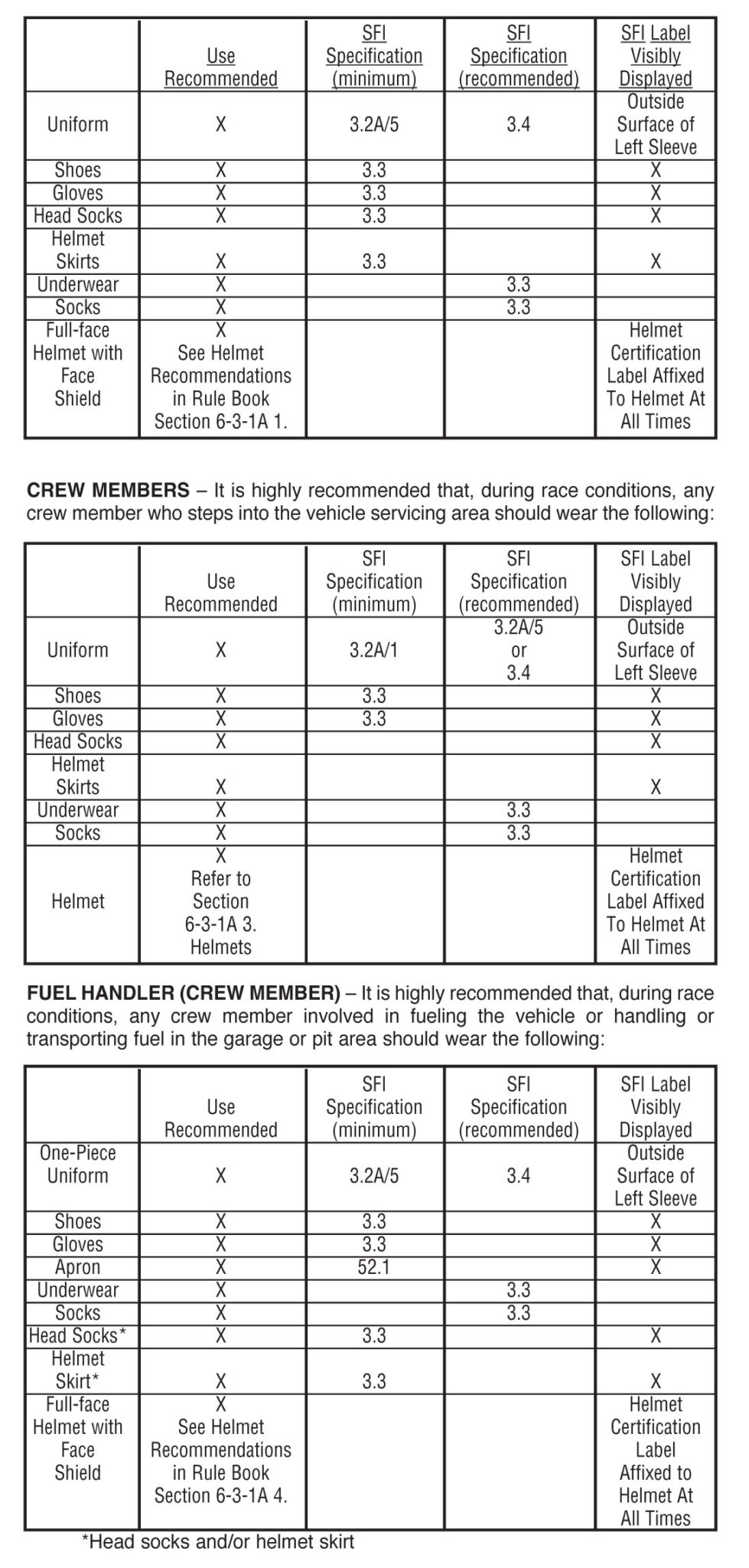
6-3-1 Recommendations for Helmets / Head and Neck Restraint Devices / Systems
- Helmets
- Drivers should wear a full-face helmet, carrying at least one (1) of the following certifications:
FIA 8860-2010
FIA 8860-2018
Snell SA 2015
Snell SA 2020
SFI 31.1/2005
Helmet certification (label) should be affixed to the helmet at all times.Helmets should be fitted with the following system:
Eject™ Helmet Removal System - The driver should wear the helmet in accordance with the directions provided by the helmet supplier and/or manufacturer. Any modification to the helmet for any purpose should not detract from its effectiveness. Helmet surface protrusions such as visor tear-off posts should be removed.
- During Race conditions, any crew member who steps into the vehicle servicing area, if any, should wear a helmet.Helmets should be fitted with the following system:
Eject™ Helmet Removal System - During Race conditions, any crew member involved in fueling the vehicle should wear a full-face helmet with a covering face shield and a fire resistant head sock or helmet skirt. It is recommended that the head socks and/or helmet skirts meet the SFI 3.3 specification and must display a valid SFI 3.3 label.
- IT IS THE RESPONSIBILITY OF THE DRIVER/CREW MEMBER, NOT THE TRACK OFFICIALS OR THE PROMOTER, TO ENSURE THAT HIS/HER HELMET IS APPROVED, CORRECTLY WORN, MAINTAINED, AND PROPERLY USED.
- Drivers should wear a full-face helmet, carrying at least one (1) of the following certifications:
- Recommendations for Head and Neck Restraint Devices / Systems
- At all times during an Event (practice, qualifying and competition), drivers should connect their helmet to a NASCAR-accepted head and neck restraint device/system which is SFI-approved and acceptable to Track Officials. The device should meet the SFI 38.1 specification and should display a valid SFI 38.1 label. The head and neck restraint
device/system, when connected, should conform to the manufacturers mounting instructions, and it should be configured, maintained and used in accordance with the manufacturer’s instructions. - IT IS THE RESPONSIBILITY OF THE DRIVER, NOT TRACK OFFICIALS, OR THE PROMOTER, TO ENSURE THAT HIS/HER DEVICE/SYSTEM IS SFI-APPROVED, DISPLAYS A VALID SFI LABEL, IS CORRECTLY INSTALLED, MAINTAINED AND
PROPERLY USED. - The following are the SFI-approved Head and Neck Restraint Devices/Systems that are currently acceptable:
Device Model Option HANS Professional Series Fixed or Sliding Tethers HANS Extra/Economy Series Fixed or Sliding Tethers HANS Pro Ultra Sliding Tethers HANS Sport Series Fixed or Sliding Tethers HANS Sport II Series Sliding Tethers HANS Stilo HANS Zero Sliding Tethers Simpson (formerly Hutchens) Hybrid Fixed Tethers Simpson Hybrid Pro, Carbon Fixed Tethers
- At all times during an Event (practice, qualifying and competition), drivers should connect their helmet to a NASCAR-accepted head and neck restraint device/system which is SFI-approved and acceptable to Track Officials. The device should meet the SFI 38.1 specification and should display a valid SFI 38.1 label. The head and neck restraint
6-3-2 Recommendations for Seat Belts
- IT IS THE RESPONSIBILITY OF THE DRIVER TO ENSURE THAT HIS/HER SEAT BELT RESTRAINT SYSTEM AND ALL COMPONENTS SHOULD BE SFI 16.5- APPROVED OR 16.6-APPROVED -AND LABELED, CORRECTLY INSTALLED, IN ACCORDANCE WITH MANUFACTURER INSTRUCTIONS MAINTAINED AND PROPERLY USED.
Installation guide: https://www.schrothracing.com/doc-share/competition_instructions.pdf
- Each vehicle should be equipped with an SFI 16.5-approved, minimum 6-point seat belt restraint system and display a valid SFI 16.5 label. It is recommended that a SFI 16.6-approved seat belt restraint system that displays a valid SFI 16.6 label be used. When the 16.6-approved seat belt system is used it should be either a 7 point or 9 point system only. The shoulder harness and lap belt assembly should not be more than three (3) inches (nominal) in width. The shoulder harness should not be less than two (2) inches wide (nominal) as it passes over the head and neck restraint device. The shoulder harness and lap belt assembly must not be more than three (3) inches (nominal) in width. Seat belt restraint systems should have a latching mechanism attached to the lap belt or, if a cam lock latching mechanism with a 5-point belt configuration is used, it should be attached to the lap belt or the shoulder harness. If the cam lock latching mechanism is used with a 6-point belt configuration, then it may be attached to the anti-submarine belt(s). This latching mechanism should provide a common connection and release for the lap belt,
shoulder harnesses and the anti-submarine belts, and should be designed with a quick and easy one-handed, gloved release of all belts in all conditions. It should have one (1) of the two (2) following release designs:- Latch/Lever Release: Utilizes a lever opening away from the body in a right to left hand movement, parallel to the lap belt with complete release of all belts. The lever should have a provision to prevent an unintentional release.
- Cam Lock Release: A circular handle or raised surface that turns in both directions for a motion of not less than 30 degrees before completely releasing all belts. A downward facing tab or toggle may be used, provided that its length does not extend more than 1/2 inch beyond the outer diameter of the release mechanism unless a provision to prevent unintentional rotation or release is provided.
- The seat belt restraint system should be installed in accordance with the directions provided by the system supplier and/or manufacturer. In addition, please note the following guidelines:
- Lap belts should be installed and used in such a manner that, when secured to the latching mechanism, the seat belt webbing travels in a straight, clear and free path from the belt mount through the seat opening to the latching mechanism. Lap belt mounts should be able to swivel without binding or interference. When the driver is buckled in the seat, the free end of the seat belt webbing should rest in a position clearly aligned over the seat belt webbing entering any adjustment or latch release hardware.
- On the left lap belt, if a roller adjuster is used, it should have tension springs installed and it should be attached to and be a part of the latch release mechanism directly without any webbing loop. The roller adjuster should not be attached to the lap belt mounting tab at the frame. A 3-bar slider, threaded to the manufacturer’s instructions, may be used for the left lap belt length adjustment, in the absence of the roller adjuster. The 3-bar slider should be positioned outside the seat opening and as close to the mounting tab as possible. On the right lap belt, if a roller adjuster is used, it should have tension springs installed and the adjuster may be located anywhere on the belt except at the frame mounting tab. A webbing link may be used to connect the roller adjuster to the latching mechanism or a 3-bar slider, threaded to the manufacturer’s instructions, may be used for the right lap belt length adjustment, in the absence of the roller adjuster. The 3-bar slider
should be positioned outside the seat opening and as close to the mounting tab as possible. Wrap-around style lap belt mounts and clip-on/hook/eyebolt style mounts should not be permitted, only tab style lap belt mounts secured with a nut and bolt should be permitted for aluminum seats. NASCAR-approved composite material seats should
use the lap belt mounts, which are integral with the seat and should be of the same mount style as approved with the seat, following the manufacturer’s instructions. - Shoulder belts should mount to horizontal shoulder bar (#7) or shoulder belt bar (#7B) only (as shown in Diagram #2B in the rear pages of the Rule Book). If shoulder belt mounting brackets are used, the shoulder belt mounting brackets should not exceed (3) three inches in length and be a minimum of 1-3/4 inches in width. The shoulder belt mounting brackets should be made of solid magnetic steel with a minimum thickness of 3/16 inch welded to the horizontal shoulder bar (#7) or shoulder belt bar (#7B). The shoulder belt mounting holes should have a minimum edge-to-hole distance of 1/4 inch. If the shoulder belt bar (#7B) is used, and the center-to-center distance from the horizontal shoulder bar (#7) is more than four (4) inches, then the shoulder belts
should mount directly to the shoulder belt bar (#7B) or to tabs welded directly to the shoulder belt bar (#7B). The opening in the seat for this type of belt should be either a single or double open slot with a finished inside edge or a grommet installed. Only individual shoulder harness belts should be permitted. Y-type shoulder harnesses should not be permitted. Wrap-around shoulder harness mounts may be permitted provided the belts do not cross behind the driver and all wrap-around mount style shoulder belts should be retained by a guide on horizontal shoulder bar (#7) or shoulder belt bar (#7B) to prevent lateral movement of the belt on the roll bar. Shoulder belts may cross behind
the driver provided they use a tab-style mount and not a wrap-around mount. The seat opening for these crossed shoulder belts should be a single, open slot with a finished inside edge or a grommet where the shoulder belts cross behind the driver. Each shoulder belt using a tab mount should use an individual mounting tab or a steel sleeve welded
through horizontal bar (#7) or shoulder belt bar (#7B) and be secured with a nut and bolt. Roller adjusters on the shoulder harnesses should have tension springs installed. Sternum or cross belts using metal or hard surface hardware should not be permitted. - Anti-submarine belts should be mounted to the seat frame or a steel reinforced seat bottom mount. Either wrap-around or tab-style antisubmarine belt mounts will be permitted on 5-point or 6-point belts and should be installed in accordance with the directions provided by the system supplier and/or manufacturer.
- The manufacturers label should not be located under the adjusting mechanism when the driver is buckled in the seat and has tightened the seat belts and shoulder harness. If the label is under the adjusting mechanism, the label may be removed and relocated in a manner that does not affect the integrity of the belt material. The date of manufacture should remain visible on the belt at all times. Seat belt restraint systems should not be used beyond two (2) years after their date of manufacture.
- The driver should use the seat belt restraint system at all times on the racetrack, in accordance with the instructions and/or recommendations of the system supplier and/or manufacturer, as set forth above.
- The SFI 16.5-approved, and 16.6-approved seat belt restraint systems will remain acceptable until their expiration date which is two (2) years after the date of manufacture. The seat belt restraint systems should be used as a complete restraint system. Brands should not be mixed.
6-3-3 Recommendations for Seats and Seat Components
- IT IS THE RESPONSIBILITY OF THE DRIVER, NOT THE TRACK OFFICIALS OR THE PROMOTER, TO ENSURE THAT HIS/HER SEAT, HEADREST/HEAD SURROUND ASSEMBLY, AND ALL SEAT COMPONENTS ARE CORRECTLY INSTALLED, MAINTAINED AND PROPERLY USED.
- Each vehicle should be equipped with an SFI 39.1 approved seat and headrest/head surround assembly displaying valid SFI 39.1 labels and be acceptable to Track Officials. Custom-manufactured aluminum seats constructed from solid aluminum sheet material from the seat bottom to above the driver’s shoulders, may be permitted if acceptable to Track Officials. Holes and/or other modifications that, in the judgment of Track Officials, were made with the intent of weight reduction should not be permitted. Composite material seats may be permitted. Seats constructed of multiple materials, including composite materials, should be SFI-approved and acceptable to Track Officials.
- All seat interiors should be lined with inserts and/or padding meeting the SFI 45.2 specification and display a valid SFI 45.2 label. Any additional non-SFI 45.2 insert/padding materials should not exceed a minimum thickness of 1/2 inch. No gaps or non-SFI 45.2 specification material(s) should be present between the seat structure and driver’s uniform in the area directly under the driver with the exception of standard seat cover upholstery (1/4 inch thick maximum) or flame retardant knit material. A minimum thickness of 3/4 inches of insert/padding meeting the SFI 45.2 specification should be used in this area directly under the driver. The area directly under the driver extends from the driver’s waist (belt line) forward to the front edge of the sub-strap pass through
holes or four (4) inches forward of the lap belt mount, whichever is greater, as well as extends five (5) inches to both the left and right of the driver’s centerline. - The seat and headrest/head surround assembly should be installed in accordance with the directions provided by the system supplier and/or manufacturer. SFI 39.1 seats and headrest/head surround assemblies should not be modified or altered. The back of the seat, at shoulder level, should be positioned as close to the horizontal shoulder bar (#7) as possible.
- All seats should have padded seat leg extensions on the left and right side. Leg extensions should be securely mounted to the seat and vehicle structure. It is recommended that the padding meet the SFI 45.2 specification and display a valid SFI 45.2 label. Composite material seat leg extensions should meet the SFI 56.1 specification for flammability. All leg extension padding and seat inserts, padding, coverings and/or upholstery should be flame retardant.
- A headrest/head surround assembly, acceptable to Track Officials, should be used. Headrests/head surround assemblies should be designed to provide rigid support around both sides of the helmet and across the back of the helmet and to the forward most point of the helmet chin bar. Extra length on the head surround should also account for forward head motion during impact. The left side of the headrest/head surround assembly may be shortened to permit egress of the driver but should not be shortened to a location rearward of the helmet chin bar. Foam, tape or other non-original coverings should not be added to the headrest without the approval of the seat manufacturer and should be acceptable to Track Officials. The headrest/head surround assembly should be rigidly bolted to the top of the seat and/or roll cage and should not extend into the window opening beyond the area defined by the upper roll cage using a minimum of 5/16
inch diameter bolts, except for the composite seats. Steel brackets welded to the roll cage should be a minimum 1/8 inch thick and aluminum brackets welded to the headrest/head surround assembly should be a minimum 3/16 inch thick. All bolts should have a minimum of 3/4 inch of metal from the center of the mounting bolt to the edge of the bracket. In addition, it is recommended that the headrest/head surround assembly be bolted to the shoulder supports (if used) with minimum 3/16 inch thick brackets and a minimum 5/16 inch diameter bolts. All headrests should be fabricated in a rigid construction and of materials which provide adequate support in an impact. - All headrest/head surround assemblies should be lined with inserts and/or padding meeting the SFI 45.2 specification and display a valid SFI 45.2 label. The headrest/head surround assembly should be padded with flat impact absorbent material, a minimum of four (4) inches thick on the right side and a minimum of 2-1/2 inches thick on the left side, meeting the SFI 45.2 specification.
- Optional strap-type headrest supports or nets should be equipped with a quick release fastener accessible by the driver.
- The upper seat back should be secured to horizontal shoulder bar (#7) or to a bracket that is secured to horizontal shoulder bar (#7) with a minimum of three (3) high quality, 5/16 inch minimum diameter bolts through the horizontal shoulder bar (#7). For aluminum seats, if a seat bracket is used to attach the seat to the horizontal shoulder bar (#7), the bracket should be constructed using a minimum of 3/16 inch thick metal plate, and it should have a minimum of 3/4 inch of metal from the center of the mounting bolt to the edge of the bracket or the bracket may utilize the composite seat bracket design. For composite seats, the seat bracket should attach the seat to the horizontal shoulder bar (#7) and should be constructed from magnetic steel.Minimum upper seat bracket thicknesses:
Hendrick: 0.090 inch
Sabelt: 3/16 inch
Sparco: 3/16 inchThe magnetic steel seat bracket to be used with a composite seat should be constructed according to the manufacturer’s instructions, including all required gussets and reinforcements. All gussets should be solid and should run from the centerline of the seat mounting hole to the centerline of the roll cage mounting hole. The outer diagonal gusset edge should be straight unless the gusset is relieved to make room for the horizontal shoulder bar (#7). Holes and or other modifications that, in the judgment of Track Officials, were made with the intent of weight reduction should not be permitted.The seat bracket should be fastened to the seat with a minimum of four (4) high quality 5/16 inch minimum diameter bolts for aluminum seats manufactured with four (4) mounting holes. Aluminum seats manufactured with three (3) mounting holes for the seat bracket should be fastened to the seat bracket with a minimum of three (3), high quality 5/16 inch minimum diameter bolts. Composite seats should be fastened to the seat bracket with a minimum of three (3), high quality 5/16 inch minimum diameter bolts. - The seat bottom should be secured to the vehicle(s) frame/roll cage assembly with a tubular seat frame in a symmetrical fashion with a minimum of two (2) high quality 5/16 inch minimum diameter bolts per side. Seat mount brackets or mounting systems welded to the seat frame should be a minimum of 1/4 inch thick. All mounting brackets should have a minimum of 1/2 inch of metal from the center of the mounting bolt to the edge of the bracket. All seat mounting brackets, welded to the frame rail, frame crossmembers, floors, roll bars or removable seat mounting frame assemblies, should be made of a minimum of 1/4 inch magnetic steel if single shear or a minimum of 3/16 inch if double shear configuration is used. If a slotted mount is used to mount the seat to the seat frame, the seat should be bolted to the seat frame bracket using an additional bolt to prevent sliding. Adjustable magnetic steel inserts (slugs) may be used to prevent sliding as an alternative to the slotted type mount with the additional bolt. When mounting through the aluminum seats or brackets large diameter washers should be used.
- The seat shoulder support angle should not exceed 25 degrees from vertical when measured where the driver’s shoulder contacts the seat with the seat installed in the vehicle. Additional angle may be added to the bottom of the shoulder support for driver arm clearance, if necessary. The interior shoulder support surface should be positioned perpendicular to the seat back in a plan view.
- Rib/chest support structures, if used, should not interfere with the natural ingress and egress of the driver from the seat. Rib/chest support structures, if used, should provide full coverage from the seat back to the front of the driver’s chest. Partial rib/chest supports constructed of foam, meeting the SFI 45.2 specification, may be permitted. Rib/chest support structures should not continue forward past the front of the driver’s chest and should not curve or wrap around the front of the driver’s chest. Rib/chest support foam, meeting the SFI 45.2 specification may curve or wrap around the front of the driver’s chest.
6-4 Window Net Recommendations
- A window net meeting the SFI 27.1 specification and displaying a valid SFI 27.1 label should be installed in the driver’s side door window opening and should be positioned to cover the entire window opening. A window net should not be used beyond two (2) years from the date of manufacture.
- The window net should be a rib type, made from minimum 3/4 inch, maximum one (1) inch wide material with a one (1) inch square opening between the ribs. The minimum window net size should be 22 inches wide by 16 inches high. The forward edge of the window net, when in the closed position, should be in line or forward of the steering wheel.
- All upper and lower window net mounts should be a minimum 1/2 inch diameter solid magnetic steel rod or a minimum one (1) inch wide by 3/16 inch thick flat magnetic steel with mounts welded directly to the roll cage. The window net, when in the closed position, should fit tight and be secured with a lever-type quick release latch acceptable to Track Officials. The lever should be secured by a detent ball in the lever and may be supplemented by a Velcro® fastener only; pins or clips should not be permitted. The latch should be mounted at the top in the front to roof bar (#3) or at the top of front roll bar leg (#2A) near roof bar (#3) and release from the inside.All safety gear and safety equipment installation must be acceptable to SMS Officials.All Stafford Motor Speedway SK Modifieds®, Late Models, and SK Lights are required to have the following driver side door bar anti-intrusion plates installed:A magnetic steel anti-intrusion plate made from a minimum thickness of .080 sheet must be securely welded to the outside of the left side door bars. The anti-intrusion plate(s) must fill the area between the horizontal centerlines of the top and bottom door bars, and vertical centerlines of main roll bar, and the left front roll bar leg. The plate(s) must be formed to match the curvature of the door bars. Individual plates, if used, should be made as large as possible. All plate(s) must have the corners fastened / welded. To facilitate emergency removal of the left side door bars, the anti-intrusion plate(s) must have six (6), 2-1/8 inch diameter holes cut in the anti-intrusion plate, with three (3) holes forward of the front vertical supports and three (3) holes rearward of the rear vertical supports in the following locations:The upper two (2) holes must be centered vertically between the left side door bars, at an on-center distance of three (3) inches from the center of the front vertical support and the rear vertical support.The middle two (2) holes must be centered vertically between the left side door bars, at an on-center distance of three (3) inches from the center of the front vertical support and the rear vertical support.The lower two (2) holes must be centered vertically between the left side door bars, at an on-center distance of three (3) inches from the center of the front vertical support and the rear vertical support.
Car Appearance
Owner/Driver/Crew/Team Members
Provisional Starting Positions
Past Champions Provisional Starting Position
Past SK Light Champion Provisional (SK Feature)
Promoters Option
Rookie Status
All divisional Rookies must have a yellow stripe on their rear bumper during all practice, qualifying and feature events. The yellow stripe must be at least half the length of the rear bumper. In order to be considered for the NAPA and R.A.D. Auto Machine Rookie of the Year (R.O.Y.) Awards, a driver must compete in at least 75% of the feature events during the course of the current season. Rookies may not have another driver qualify a car for them.
R.O.Y. Winner Obligations
The current R.O.Y., as determined from the previous season, will be awarded $100 for each event attended, starting with the first event of the current calendar year and continuing each consecutive event until the total award amount for each division is distributed. To be eligible for the R.O.Y. Award bonus payments, the driver must attempt to qualify and compete in 75% of a division’s feature events.
Victory Lane Podium Obligations
Tire Testing Agreement
2024 Tire Testing Agreement
All Stafford Speedway weekly drivers are required to review and sign this agreement, to compete in 2024.
The following rule is in place for all divisions competing at Stafford Speedway in 2024
20E – 10.8.1 Tires – Physical Requirements
No chemical treating or altering of tires allowed. A participant competing in any race at SMS specifically agrees that he/she acknowledges it is illegal to soak or treat racing tires and that said soaking or treatment of racing tires is subject to suspension.
Tire Testing Policy
- – Stafford Speedway will randomly test tires for, but not limited to, chemical treating, altering, and soaking throughout the 2024 season.
- – Tires may be sampled at any time and will be tested at random throughout the 2024 season
- – An Independent lab test will be used to check tires for chemical treatment, altering, etc..
- – Blue Ridge Race Labs, Inc will be responsible for all lab tests
- – Tires will not be submitted to any other lab
- – Tires are deemed to be treated or altered if they do not meet the manufacturer’s (Hoosier Tire) benchmark.
- – Appeals are not permitted, official decisions are final.
- – Any drivers found to have a treated tire or tires will be disqualified from the event and receive a $1,000 fine. Repeat violations will result in more severe penalties.
In signing this agreement, I confirm I have read and understand that Stafford Motor Speedway does not allow soaking, chemically treating, altering, etc.. of race tires. I understand that any tires that do not meet the manufacturer’s benchmark will result in a disqualification and further penalties. I agree to race at Stafford Motor Speedway with the knowledge of this agreement and the tire testing policy stated within this agreement. I understand and agree that all officials decisions are final and that there is no appeal process, lab test results will be official.
Print Name: _____________________________
Date: __________________________
Signature: ______________________________
Division & Car Number: ___________________
Tire App: How To Guide
Site URL: driver.staffordspeedway.com
The tire app is mobile only, please access from your mobile device, access using your mobile browser
Please contact tires@staffordspeedway.com with any questions or if you need assistance
Set your Tire password
All registered drivers will receive an email from Stafford Speedway to set your password
Don’t know your login?
If you did not receive a set password email or can’t find your set password email, navigate to driver.staffordspeedway.com and select Forgot Password
The driver’s email provided for 2023 number registration is the email your account has been created for.
Sign-In
Using your email and password, login to your profile

View your driver profile
Upon sign-in you will be able to access your driver profile, this includes your unique QR code.

When to use your QR code?
Your QR code will be required when you purchase tires and when you add your tires to inventory. After you sign-in for that night’s event your QR code will become active and display how many tires you have available for purchase.

How to access the menu
To access the menu options, select the 3 lines on the upper right corner of your screen.
Menu options include:
- My QR Code
- Tire Inventory
- Settings
- Sign Out
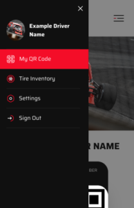
What if you compete in multiple divisions?
If you compete in multiple divisions, your account will display a separate QR code for each division you compete in. Be sure to scan the correct code when you are purchasing and inventorying your tires

How do I see my Tire Inventory
Select Tire Inventory in the menu to view the tires you have in your inventory. There is also a print option in this section.
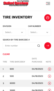
Weekly Race Payouts & Point Fund
Additional Contingency Bonus Money in Italics
Visit the Track Partners page for full list of Contingency Partners
SK Modified®
| 1st | $1,500 + ($325) |
| 2nd | $900 + ($400) |
| 3rd | $700 + ($125) |
| 4th | $600 |
| 5th | $475 |
| 6th | $375 |
| 7th | $350 |
| 8th | $325 |
| 9th | $300 |
| 10th | $290 |
| 11th | $275 |
| 12th | $260 |
| 13th | $245 |
| 14th | $230 |
| 15th | $210 |
| 16th | $200 |
| 17th | $185 |
| 18th | $180 |
| 19th | $175 |
| 20th | $170 |
| 21st | $160 |
| 22nd | $155 |
| 23rd | $150 |
| 24th | $150 |
| Total | $9,135 |
Late Model
| 1st | $800 + ($150) |
| 2nd | $500 + ($125) |
| 3rd | $400 + ($100) |
| 4th | $350 |
| 5th | $275 |
| 6th | $250 |
| 7th | $225 |
| 8th | $200 |
| 9th | $185 |
| 10th | $180 |
| 11th | $175 |
| 12th | $170 |
| 13th | $165 |
| 14th | $160 |
| 15th | $155 |
| 16th | $150 |
| 17th | $145 |
| 18th | $140 |
| 19th | $135 |
| 20th | $130 |
| 21st | $125 |
| 22nd | $120 |
| 23rd | $120 |
| 24th | $120 |
| Total | $5,750 |
SK Light
| 1st | $350 + ($400) |
| 2nd | $250 + ($175) |
| 3rd | $225 + ($175) |
| 4th | $175 |
| 5th | $160 |
| 6th | $150 |
| 7th | $140 |
| 8th | $130 |
| 9th | $125 |
| 10th | $120 |
| 11th | $115 |
| 12th | $110 |
| 13th | $105 |
| 14th | $100 |
| 15th | $95 |
| 16th | $90 |
| 17th | $85 |
| 18th | $80 |
| 19th | $75 |
| 20th | $70 |
| 21st | $70 |
| 22nd | $70 |
| 23rd | $70 |
| 24th | $70 |
| Total | $3,430 |
Limited Late Model
| 1st | $350 + ($125) |
| 2nd | $250 + ($100) |
| 3rd | $225 + ($100) |
| 4th | $175 |
| 5th | $160 |
| 6th | $150 |
| 7th | $140 |
| 8th | $130 |
| 9th | $125 |
| 10th | $120 |
| 11th | $115 |
| 12th | $110 |
| 13th | $105 |
| 14th | $100 |
| 15th | $95 |
| 16th | $90 |
| 17th | $85 |
| 18th | $80 |
| 19th | $75 |
| 20th | $70 |
| 21st | $70 |
| 22nd | $70 |
| 23rd | $70 |
| 24th | $70 |
| Total | $3,305 |
Street Stock
| 1st | $250 + ($100) |
| 2nd | $175 + ($125) |
| 3rd | $150 + ($75) |
| 4th | $125 |
| 5th | $100 |
| 6th | $95 |
| 7th | $90 |
| 8th | $85 |
| 9th | $80 |
| 10th | $75 |
| 11th | $70 |
| 12th | $65 |
| 13th | $60 |
| 14th | $55 |
| 15th | $55 |
| 16th | $55 |
| 17th | $50 |
| 18th | $50 |
| 19th | $50 |
| 20th | $45 |
| 21st | $45 |
| 22nd | $45 |
| 23rd | $40 |
| 24th | $40 |
| Total | $2,100 |
Special Event Payouts
Street Stock Firecracker 30
| 1st | $700 |
| 2nd | $500 |
| 3rd | $400 |
| 4th | $300 |
| 5th | $275 |
| 6th | $250 |
| 7th | $200 |
| 8th | $190 |
| 9th | $180 |
| 10th | $175 |
| 11th | $170 |
| 12th | $165 |
| 13th | $160 |
| 14th | $150 |
| 15th | $145 |
| 16th | $145 |
| 17th | $140 |
| 18th | $140 |
| 19th | $130 |
| 20th | $130 |
| 21st | $125 |
| 22nd | $125 |
| 23rd | $125 |
| 24th | $125 |
| – | – |
| – | – |
| Total |
SK Light Modified 40
| 1st | $1,750 |
| 2nd | $1,000 |
| 3rd | $800 |
| 4th | $600 |
| 5th | $500 |
| 6th | $425 |
| 7th | $400 |
| 8th | $325 |
| 9th | $300 |
| 10th | $275 |
| 11th | $250 |
| 12th | $245 |
| 13th | $240 |
| 14th | $235 |
| 15th | $230 |
| 16th | $225 |
| 17th | $220 |
| 18th | $215 |
| 19th | $210 |
| 20th | $205 |
| 21st | $200 |
| 22nd | $195 |
| 23rd | $190 |
| 24th | $185 |
| 25th | $180 |
| 26th | $175 |
| Total |
Modified Open 80
| 1st | $3,500 + ($1,500) |
| 2nd | $1,600 |
| 3rd | $1,300 |
| 4th | $1,200 |
| 5th | $1,000 |
| 6th | $975 |
| 7th | $925 |
| 8th | $875 |
| 9th | $850 |
| 10th | $825 |
| 11th | $800 |
| 12th | $775 |
| 13th | $750 |
| 14th | $725 |
| 15th | $700 |
| 16th | $660 |
| 17th | $660 |
| 18th | $660 |
| 19th | $660 |
| 20th | $660 |
| 21st | $660 |
| 22nd | $660 |
| 23rd | $660 |
| 24th | $660 |
| 25th | $660 |
| 26th | $660 |
| Total | $24,060 |
SK Modified® NAPA SK 5K
| 1st | $5,000 + ($325) |
| 2nd | $2,500 + ($400) |
| 3rd | $1,800 + ($125) |
| 4th | $1,700 |
| 5th | $1,600 |
| 6th | $1,400 |
| 7th | $1,300 |
| 8th | $1,200 |
| 9th | $1,150 |
| 10th | $1,000 |
| 11th | $1,000 |
| 12th | $900 |
| 13th | $800 |
| 14th | $700 |
| 15th | $600 |
| 16th | $550 |
| 17th | $550 |
| 18th | $550 |
| 19th | $550 |
| 20th | $550 |
| 21st | $550 |
| 22nd | $550 |
| 23rd | $550 |
| 24th | $550 |
| 25th | $550 |
| 26th | $550 |
| Total | $28,700 |
Late Model 50
| 1st | $1,200 |
| 2nd | $900 |
| 3rd | $800 |
| 4th | $700 |
| 5th | $600 |
| 6th | $500 |
| 7th | $400 |
| 8th | $375 |
| 9th | $350 |
| 10th | $325 |
| 11th | $320 |
| 12th | $300 |
| 13th | $300 |
| 14th | $295 |
| 15th | $290 |
| 16th | $285 |
| 17th | $280 |
| 18th | $270 |
| 19th | $260 |
| 20th | $250 |
| 21st | $250 |
| 22nd | $250 |
| 23rd | $250 |
| 24th | $250 |
| – | – |
| – | – |
| Total | $10,000 |
Street Stock Cleetus McFarland New England 900 Purse
| 1st | $1,000 |
| 2nd | $500 |
| 3rd | $400 |
| 4th | $300 |
| 5th | $275 |
| 6th | $250 |
| 7th | $200 |
| 8th | $190 |
| 9th | $180 |
| 10th | $175 |
| 11th | $170 |
| 12th | $165 |
| 13th | $160 |
| 14th | $150 |
| 15th | $145 |
| 16th | $145 |
| 17th | $140 |
| 18th | $140 |
| 19th | $130 |
| 20th | $130 |
| 21st | $125 |
| 22nd | $125 |
| 23rd | $125 |
| 24th | $125 |
| 25th | $125 |
| Total | $5,570 |
2024 Point Fund
